Note:
The external resistor is advised to be lower than 400Ω
when AO output current signal.
A6.31 Zero offset calibration
of AO1
For the analog output AO1 and AO2,adjust the gain if
user
need to change the display range or calibrate the gauge
outfit error.
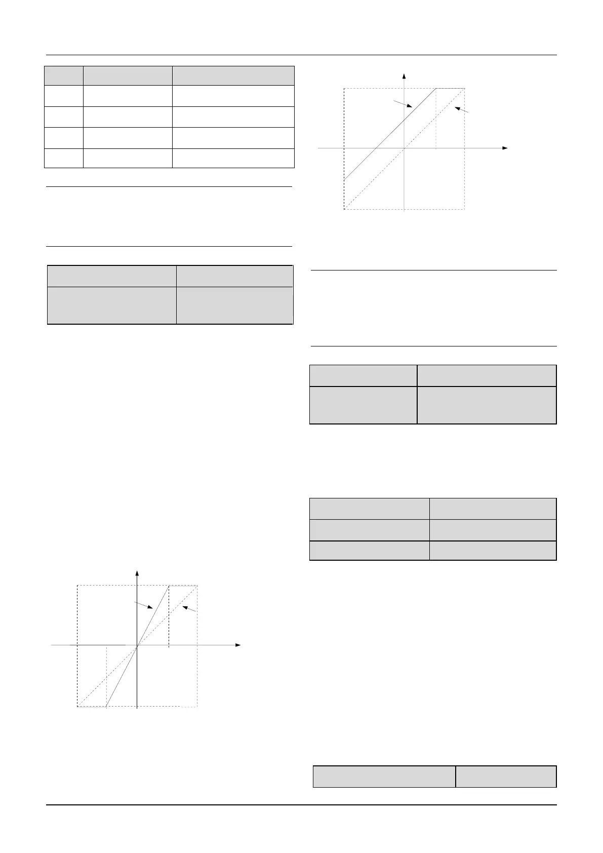
100% of zero offset of analog output is corresponding to
the maximum output (10V or 20Ma).Take output voltage
for example,the relationship between the value before
adjustment and with after adjustment is as following:
AO output value = (Gain of AO)×(value before
adjustment)+(Zero offset calibration)×10V
The relationship curve between analog output and gain
and between analog output and zero offset calibration
are as Fig.6-31 and Fig.6-32.
Fig.6-31 Relationship curve between analog
output and gain
Fig.6-32 The relationship curve between analog
output and zero offset
Note:
The parameters of gain and zero offset calibration affect
the
analog output all the time when it is chaning.
A6.33 Zero offset
calibration of AO2
The functions of analog output AO2 are totally the same
as
AO1.
A6.34~A6.36 define the time constant of AI filter.The
longer the filter time,the stronger the anti-interference
ability,but the response will become slower.The shorter
the filter time,the faster the response,but the
anti-interference ability will become weaker.
6.8 Group A7
The parameters in this group are reserved
6.9 Group A8
A8.00 Protective action of relay
Value before adjustment(V)
Value after adjustment(V)
Value before adjustment(V)
Value after adjustment(V)

 Loading...
