Percentage of
host computer
A6.26 Max. output pulse
frequency
This parameter defines the permissible maximum pulse
frequency of Y2.
A6.27 Centre point of
pulse output selection
This parameter defines different centre point mode of Y2
pulse output.
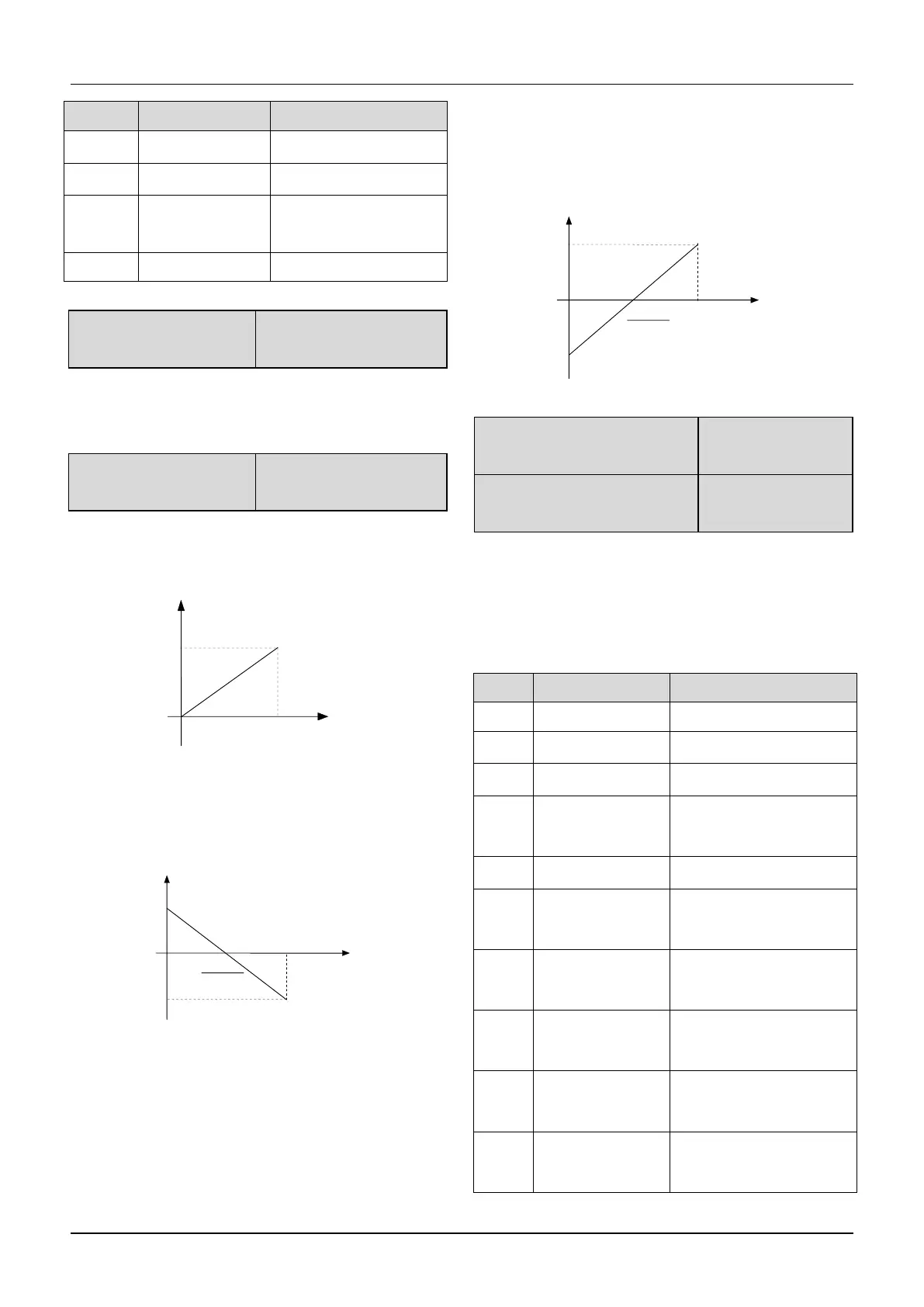
0:No centre point.Shown as following figure:
Fig.6-28 No centre point mode
All the corresponding value of pulse output frequency
are positive.
1: Centre point mode 1.Shown as following figure.
Fig.6-29 Centre point mode 1
There is a centre point in pulse output.The value of the
centre point is a half of max. output pulse frequency
(A6.26).The corresponding value is positive when the
output pulse frequency is less than centre point.
2:Centre point mode 2
There is a centre point in pulse output.The value of the
centre point is a half of max. output pulse frequency
(A6.26).The corresponding value is positive when the
input pulse frequency is greater than centre point.
Fig.6-30 Centre point mode 2
A6.28 Functions of terminal
AO1
A6.29 Functions of terminal
AO2
Refer to section 4.2 for the output characteristics of AO1
and AO2.
The relationship between the displaying range and the
output values of AO1 and AO2 is shown as Table 6-8
Table 6-8 Displaying range of Analog output
Preset frequency
(After Acc/Dec)
0~2 times of drive’s
rated current
0~2 times of motor’s
rated current
0~3 times of motor’s
rated torque
0 ~ 3 times of motor’s
rated torque
0~1.2 times of drive’s
rated voltage

 Loading...
