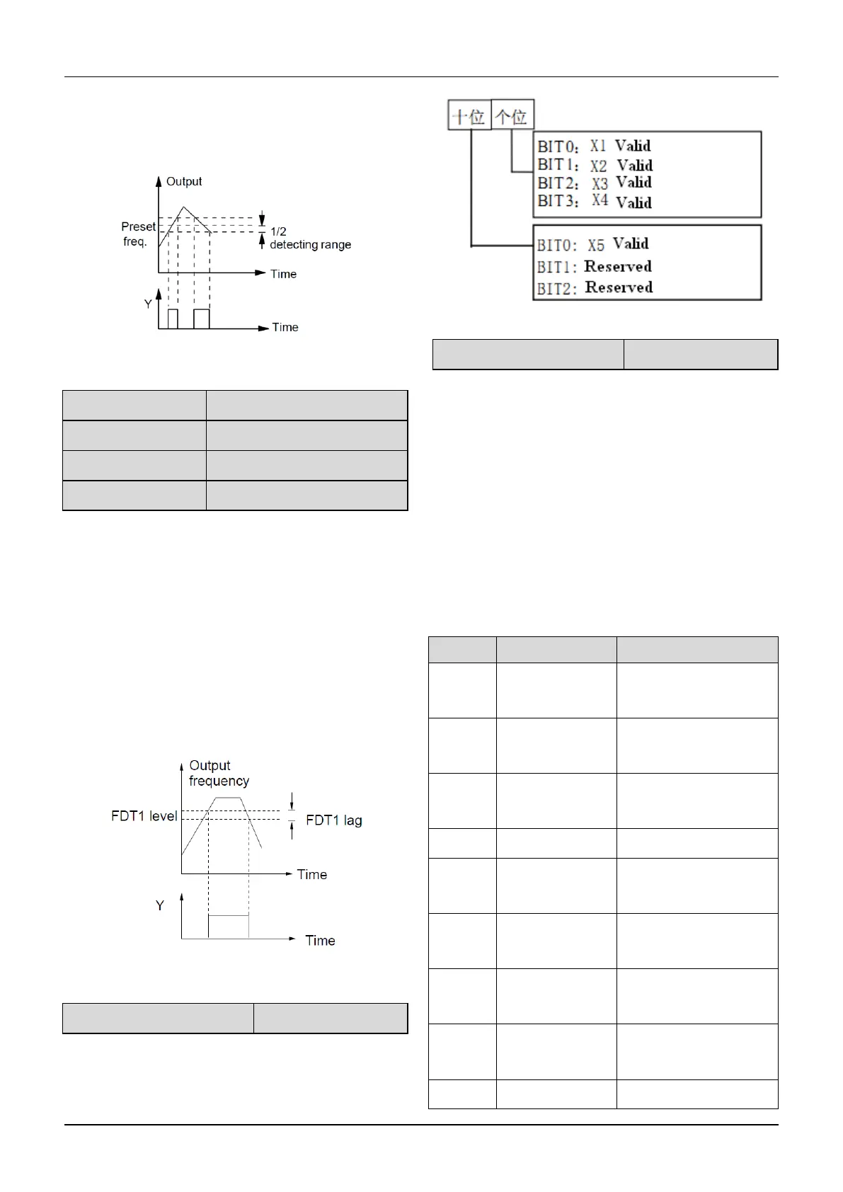
As shown in Fig. 6-23, if the drive’s output frequency is
within the detecting range of preset frequency, a pulse
signal will be output.
Fig.6-23 Frequency arriving signal
A6.20~A6.21 is a complement to the No.2 function in
Table 6-6. A6.22~A6.23 is a complement to the No.3
function in Table 6-6. Their functions are the same.Take
A6.20~A6.21 for example:
When the drive’s output frequency reaches a certain
preset frequency (FDT1 level), it outputs an indicating
signal until its output frequency drops below a certain
frequency of FDT1 level (FDT1 level-FDT1 lag), as
shown in Fig. 6-27
Fig.6-27 FDT level
A6.24 Virtual terminal setting
0~50:Y2 is used as Y terminal output; its function is the
same as Table 6-6.
51~88:Y2 function.
Pulse frequency frequency of Y2:0~Max pulse output
frequency(Defined in A6.26).
The linear relationship between the displaying range and
the output values of Y2 is shown as Table 6-7.
Table 6-7 Displaying range of Y2 terminal
0 ~ Max. output
frequency
0 ~ Max. output
frequency
Preset frequency
(After Acc/Dec)
0 ~ Max. output
frequency
0~2 times of motor’s
rated current
0~3 times of motor’s
rated current
0~3 times of motor’s
rated torque
0~1.2 times of drive’s
rated voltage

 Loading...
