Drive running
forward/reverse
The instructions of the functions in Table 6-6 as
following:
0: Drive running signal (RUN)
When the drive is in operating status, there will be
running indication signal output by this terminal.
1: Frequency arriving signal (FAR)
See A6.19.
2: Frequency detection threshold (FDT1)
See A6.20~A6.21.
3: Frequency detection threshold (FDT2)
See A6.22~A6.23.
4: Reserved.
5: Low voltage lock-up signal (LU)
The terminal outputs the indicating signal if the DC bus
voltage is lower than the low voltage limit, and the LED
displays ―P.oFF‖.
6: External stopping command (EXT)
The terminal outputs the indicating signal if the drive
outputs tripping signal caused by external fault (E015).
7: High limit of frequency (FHL)
The terminal outputs the indicating signal if the preset
frequency is higher than upper limit of frequency and the
operating frequency reaches the upper limit of
frequency.
8: Lower limit of frequency (FLL)
The terminal outputs the indicating signal if the preset
frequency is higher than lower limit of frequency and the
operating frequency reaches the lower limit of
frequency.
9: Zero-speed running
The terminal outputs the indicating signal if the drive’s
output frequency is 0 and the drive is in operating status.
10~14:Reserved.
15: drive ready (RDY)
If RDY signal is output, it means the drive has no fault,
its DC bus voltage is normal and it can receive starting
command.
16: Drive fails
The terminal outputs the indicating signal if the drive
has faults.
17~18: Reserved.
19: Torque limiting
The terminal outputs the indicating signal if the torque
reach drive torque limit or brake torque limit.
20: Drive running forward/reverse
The terminal outputs the indicating signal according to
the drive’s current running direction.
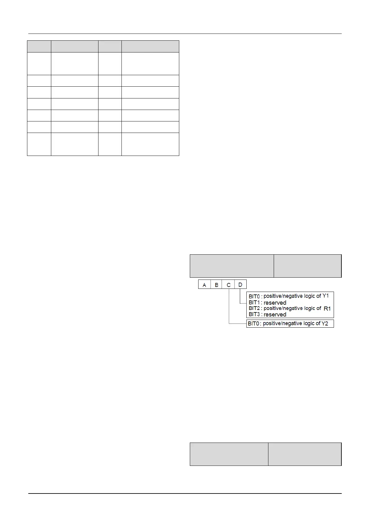
A6.18 Ouput terminal’s
positive and negative logic
Fig.6-22 Ouput terminal’s positive and negative logic
A6.18 defines the output terminal’s positive and
negative logic.
Positive logic: Terminal is enabled if it is connected to
the common terminal;
Negative logic: Terminal is disabled if it is connected to
the common terminal;
If the bit is set at 0, it means positive logic; if set at 1, it
means negative logic.
A6.19 Frequency arriving
signal (FAR)

 Loading...
