b0.13 Oscillation inhibition
coefficient
Adjust this parameter can prevent motor oscillation
when drive using V/F control.
6.11 Group b1
b1.01 V/F frequency value
F3 of motor 1
b1.02 V/F voltage value V3
of motor 1
b1.03 V/F frequency value
F2 of motor 1
b1.04 V/F voltage value V2
of motor 1
b1.05 V/F frequency value
F1 of motor 1
b1.06 V/F voltage value V1
of motor 1
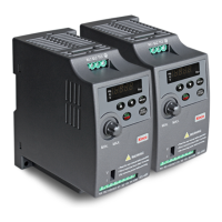
This group of parameters define the V/F setting modes
of SV100 so as to satisfy the requirements of different
loads. 3 preset curves and one user-defined curve can
be selected according to the setting of b1.00.
If b1.00 is set to 1, a 2-order curve is selected, as shown
in Fig. 6-35 as curve 1;
If b1.00 is set to 2, a 1.7-order curve is selected, as
shown in Fig. 6-35 as curve 2;
If b1.00 is set to 3, a 1.2-order curve is selected, as
shown in Fig. 6-35 as curve 3;
The above curves are suitable for the variable-torque
loads such as fan & pumps. You can select the curves
according to the actual load so as to achieve best
energy-saving effects.
Fig.6-35 Torque-reducing curve
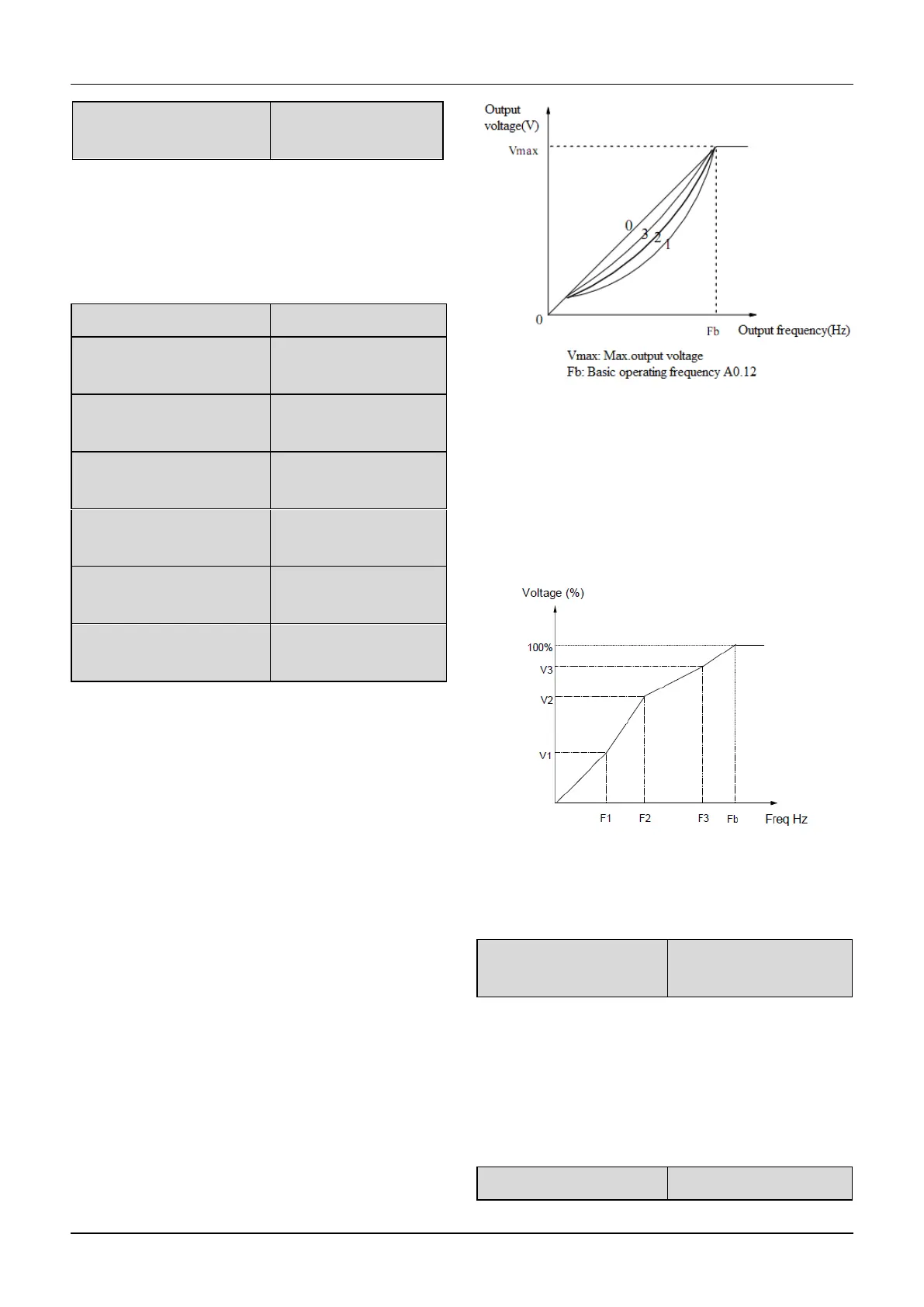
If b1.00 is set to 0, you can define V/F curve via
b1.01~b1.06, as shown in Fig. 6-36. The V/F curve can
be defined by connecting 3 points of (V1,F1), (V2,F2)
and (V3, F3), to adapt to special load characteristics.
Default V/F curve set by factory is a direct line as show
in Fig. 6-35 as curve 0.
Fig.6-36V/F curve defined by user
b1.07 Cut-off point used
for manual torque boost
b1.07 defines the ratio of the cut-off frequency used for
manual torque boost to the basic operating frequency
(defined by A0.12), as shown in Fig. 6-36 as Fz.This
cut-off frequency adapts to any V/F curve defined by
b1.00.
V1~V3: Voltage of sections 1~3
F1~F3: Freq of sections 1~3
Fb:Basic operating frequency of A0.12
 Loading...