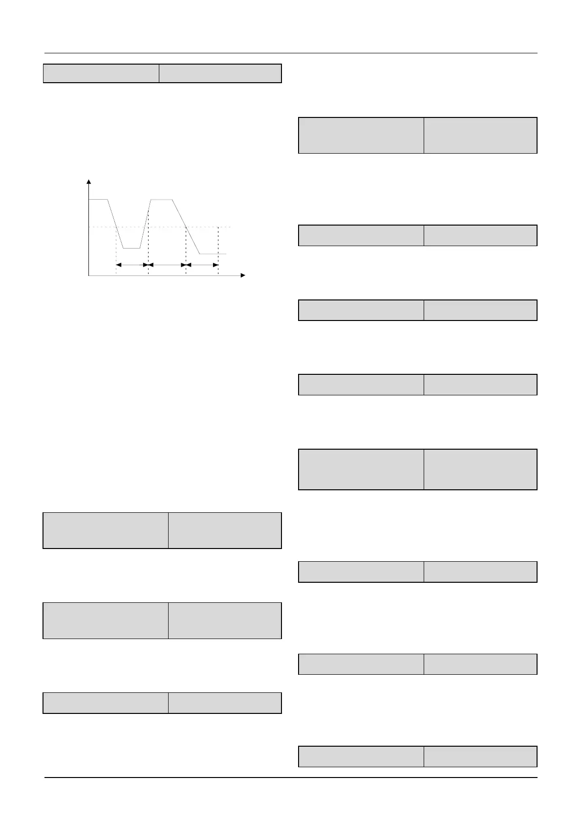
When the close-loop feedback is lower than the detected
value(C1.36) within the detected time(C1.37),the drive
will operation the action set by C1.35.The detection
sequence of close-loop feedback lost is shown in
Fig.6-45.
Fig.6-45 The detection sequence of
close-loop feedback lost
6.17 Group C2
This group of parameters is simple PLC function
(Custom-made).
6.18 Group d0
The parameters of Group d0 are used to monitor some
states of drives and motors.
d0.00 Main reference
frequency
This parameter is used to monitor main reference
frequency at normal operation mode.
d0.01 Auxiliary reference
frequency
This parameter is used to monitor the auxiliary reference
frequency at normal operation mode.
This parameter is used to monitor the frequency
combined by main reference frequency and auxiliary
reference frequency.Positive indicates running forwards,
negative indicates running reverse.
d0.03 Frequency after
Acc/Dec
This parameter is used to monitor the drive’s output
frequency(include direction) after the drive accelerating
or decelerating.
This parameter is used to monitor the drive’s output
frequency(include direction).
This parameter is used to monitor the drive’s output
voltage.
This parameter is used to monitor the drive’s output
current.
This parameter is used to monitor the percentage of
drive’s torque current that corresponding to the motor’s
rated current.
d0.08 Magnetic flux current
This parameter is used to monitor the percentage of
drive’s magnetic flux current that corresponding to the
motor’s rated current.
This parameter is used to monitor the percentage of
drive’s output power that corresponding to the motor’s
rated power.
Close-loop feedback value
 Loading...