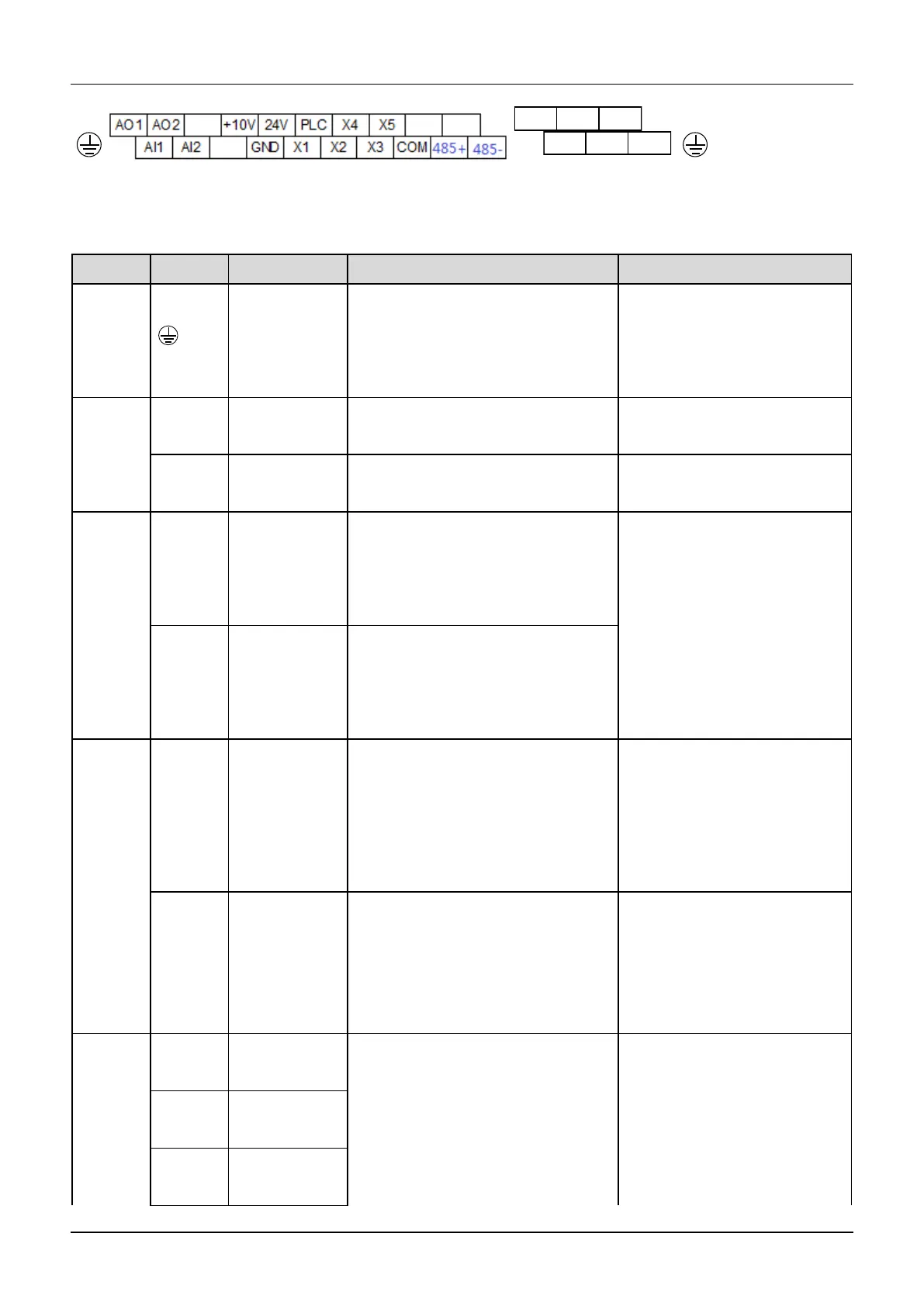
Fig.4-2 Arrangement of control terminals
Refer to table 4-3 and 4-4 for description of each terminal
Table 4-3 function list of each list
PE terminal connected to shielding
layer.Analog singal, 485
communication,motor power cable
shield can be connected here
Connected to circuit PE inside the
drive
Provide +10V power supply
Maximum output current is 5mA
GND of analog signal and 10V power
supply
Isolated from COM and CME
Can accept analog voltage/current
input, jumper AI1 can select voltage or
current input mode. (Reference ground:
GND)
Input voltage range: -10V~10V
( Input impedance 45KΩ )
Resolution: 1/4000
Input current range : 0mA~20
mA, Resolution: 1/2000(Need
jumper)
Can accept analog voltage/current
input, jumper AI2 can select voltage or
current input mode. (Reference ground:
GND)
Providing analog voltage or current
output, they are selected by the jumper
AO1. The default setting is output
voltage, refer to the function code
A6.28(Reference ground: GND)
Voltage output range: 0V~10V
Current output range:
0/4~20mA
Providing analog voltage or current
output, they are selected by the jumper
AO2. The default setting is output
voltage, refer to the function code
A6.29 (Reference ground: GND)
Voltage output range: 0V~10V
Current output range:
0/4~20mA
Multi-fun
ction
input
terminal
Multi-function
input terminal 1
Can be defined as multi-function digital
input terminal.(Refer to the A6 group,
form A6.00 to A6.06)
Optocoupler isolation input
Input resistor: R=3.3kΩ
Maximum input frequency of
X1~X6: 200Hz
Maximum input frequency of X7:
100kHz
Multi-function
input terminal 2
Multi-function
input terminal 3
 Loading...