motor. Initial braking frequency, braking delay time and
braking current are defined by A1.06~A1.08. Braking
time is the greater value between A1.09 and the effective
continuous time defined by this control terminal.
12: Coast to stop.
If the setting is 12, the function of the terminal is the
same with that defined by A1.05. It is convenient for
remote control.
13~14: Frequency ramp UP/DN.
If the setting is 13~14, the terminal can be used to
increase or decrease frequency. Its function is the same
with ▲ and ▼ keys on the panel, which enables remote
control. This terminal is enabled when A0.02=0 or
A0.04=1. Increase or decrease rate is determined by
A2.02 and A2.03.
15: Switch to panel control.
It is used to set the control mode as panel control.
16: Switch to terminal control
It is used to set the control mode as terminal control
17: Reserved.
18: Main reference frequency via AI1
19: Main reference frequency via AI2
20: Reseved
21: Reserved
22: Auxiliary reference frequency invalid.
Auxiliary reference frequency is invalid when the
terminal activate
23~26: Reserved.
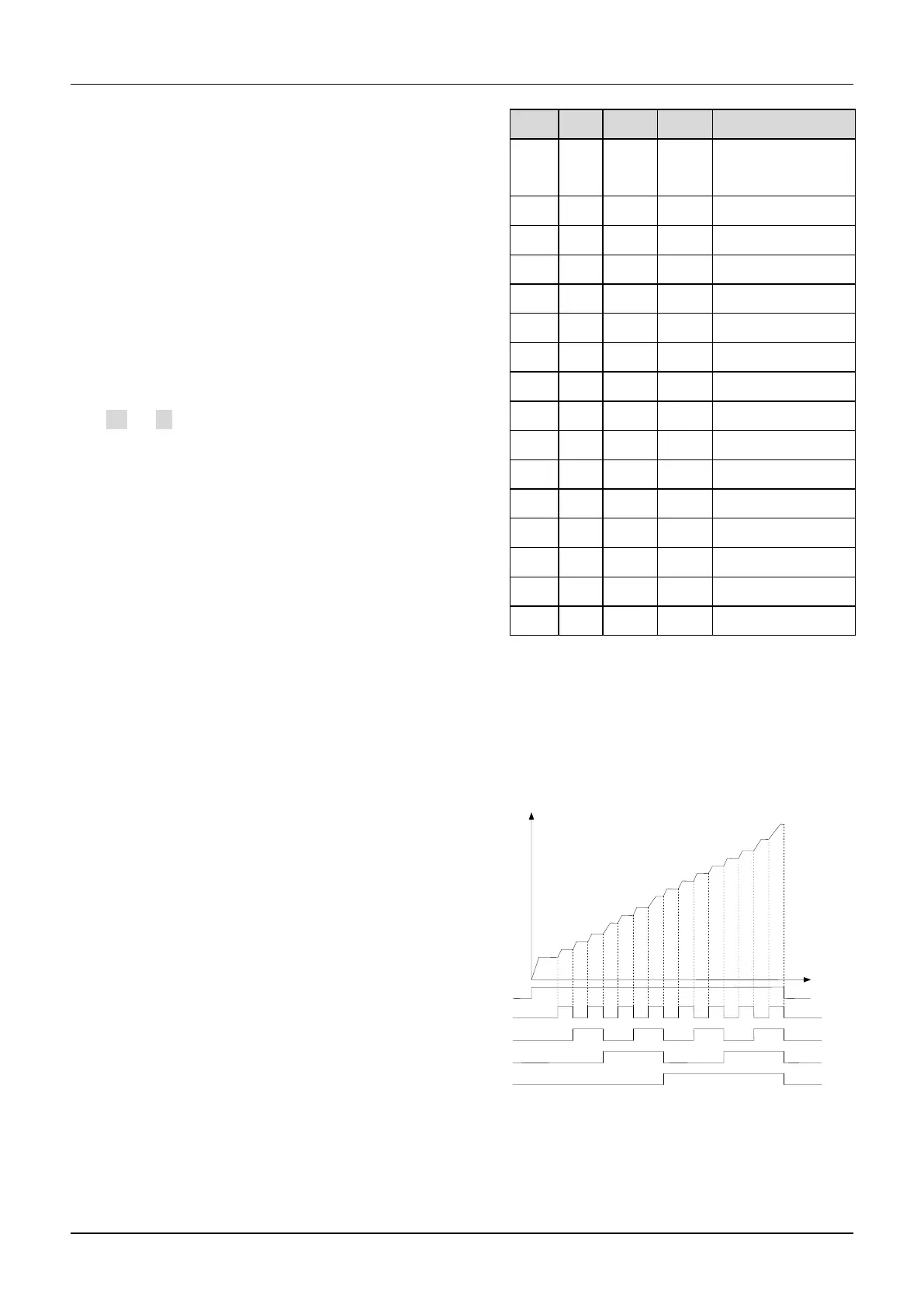
27~30: Preset frequency selection.
Up to 15 speed references can be set through different
ON/OFF combinations of these terminals K4, K3, K2
and K1.
Table 6-2 On/Off combinations of terminals
The frequency references will be used in multiple speed
operation. Following is an example: Definitions of
terminals X1, X2, X3and X4 as following:
After setting A6.00 to 27, A6.01 to 28 and A6.03 to 30,
terminals X1~X4 can be used in multiple speed
operation, as shown in Fig. 6-16.
Fig.6-16 Multi-step speed operation
31~32:Acc/Dec time selection
Table 6-3 Acc/Dec time selection
Common operating
frequency
Common
Operating
frequency

 Loading...
