As shown in Fig. 6-38, pressure reference (voltage
signal) is input via terminal AI2, while the feedback
pressure value is input into terminal AI1 in the form of
0(4)~20mA current signal. The reference signal and
feedback signal are detected by the analog channel.The
start and stop of the drive can be controlled by terminal
Xi.
The above system can also use a TG (speed measuring
generator) in close speed-loop control.
Note:
The reference can also be input via panel or serial port.
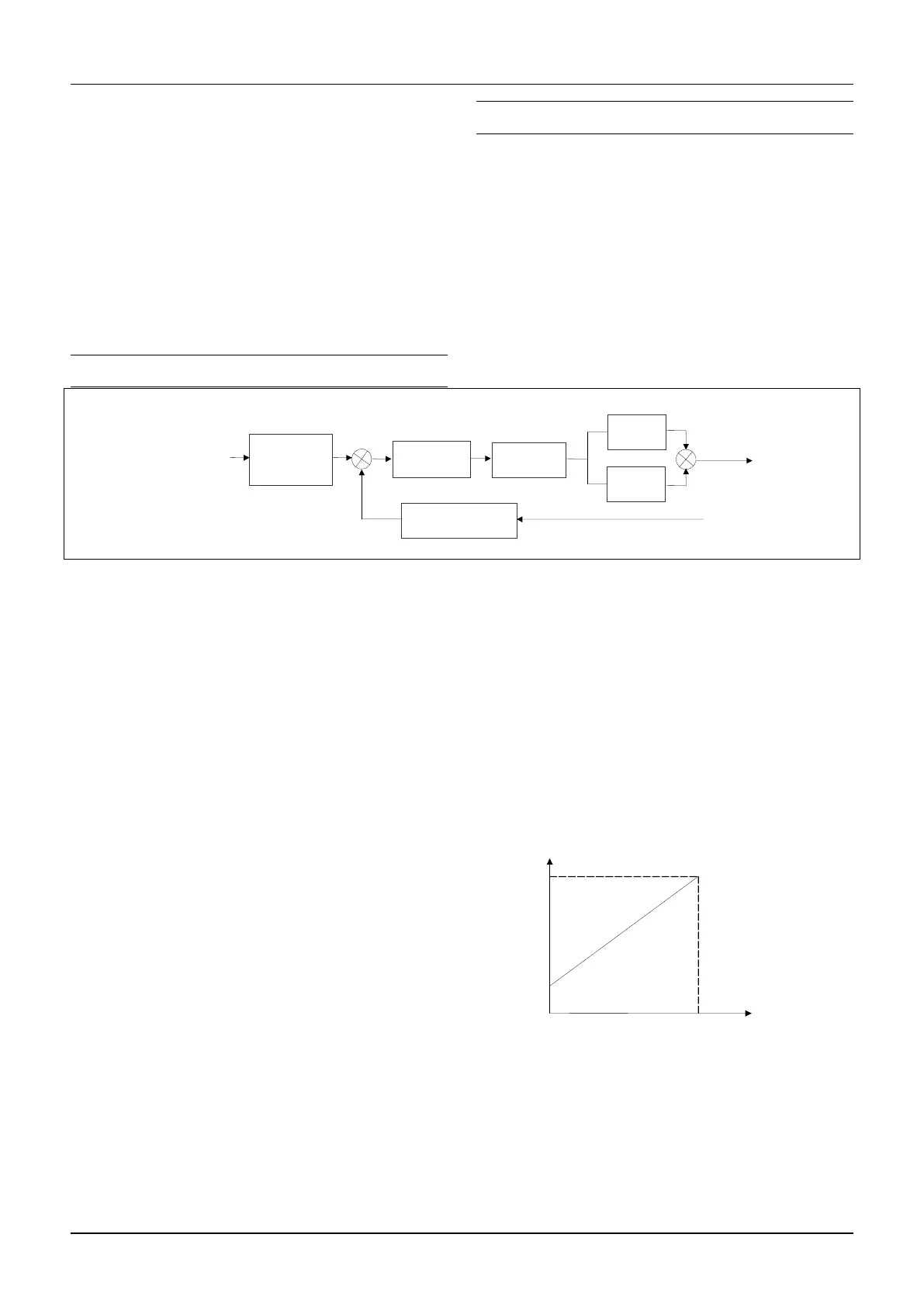
Operating principles of internal process close-loop of
SV100 is shown in the Fig. 6-39.
In the above Fig., KP: proportional gain; Ki: integral
gain
In Fig. 6-39, refer to C1.00~C1.14 for the definitions of
close-loop reference, feedback, error limit and
proportional and Integral parameters.
Fig.6-39 Principle diagram of process close-loop control
There are two features of internal close-loop of SV100:
The relationship between reference and feedback can be
defined by C1.05~C1.08
For example: In Fig. 6-38, if the reference is analog
signal of -10~10V, the controlled value is 0~1MP, and
the signal of pressure sensor is 4~20mA, then the
relationship between reference and feedback is shown
in Fig. 6-40.
Fig.6-40 Reference and feedback
After the control type is determined, follow the
procedures below to set close loop parameters.
1)Determine the close-loop reference and feedback
channel (C1.01 and C1.02);
2)The relationship between close-loop reference and

 Loading...
