Service ManualService Manual
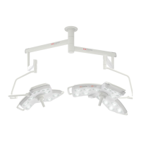
Operating Lights marLEDOperating Lights marLED
®®
E9 / E9i / E9 / E9i / E15E15
34 34 V V 1.01.0
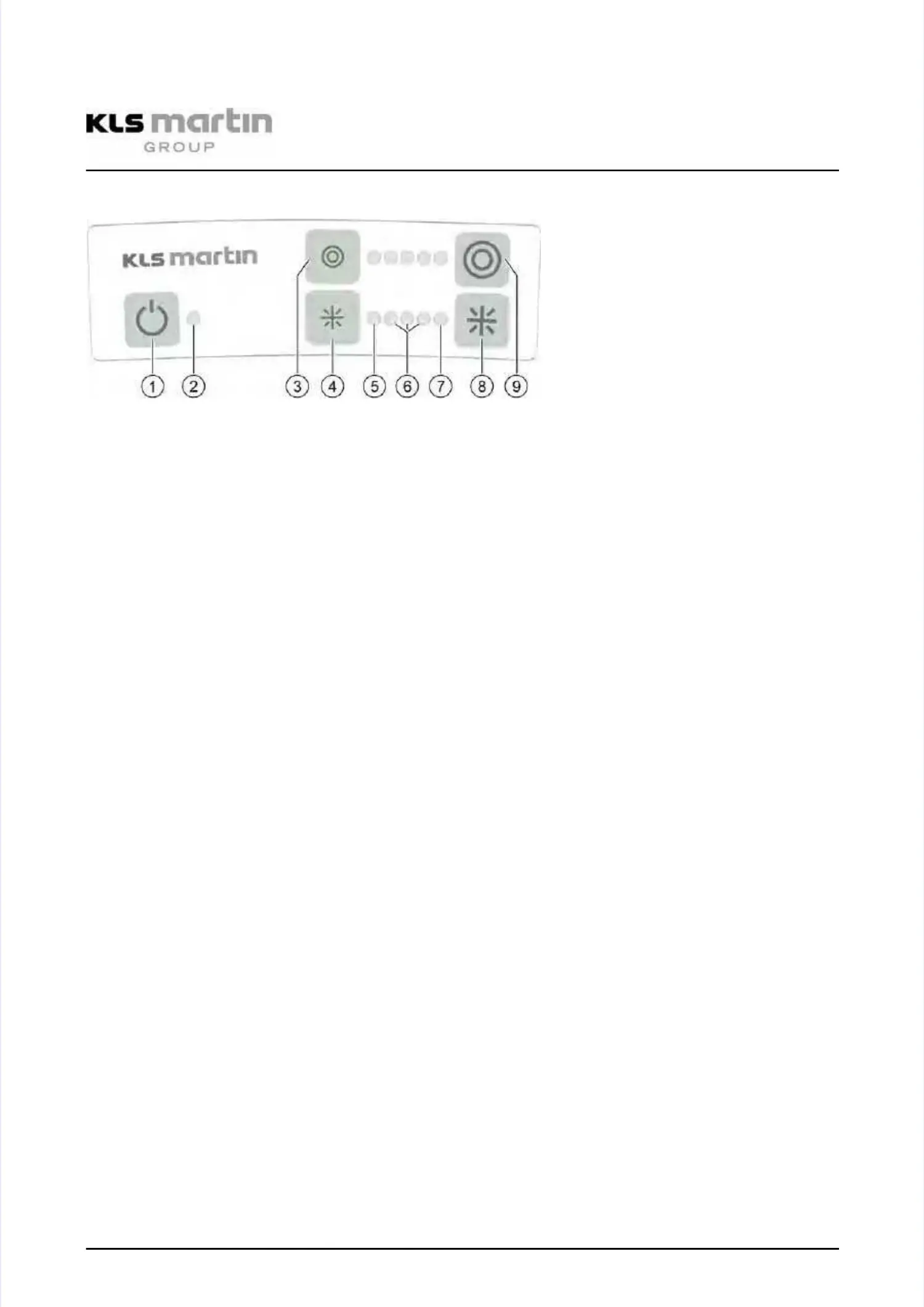
6.26.2 Display of the operating foilDisplay of the operating foil
11
ON / OFF switchON / OFF switch
22
LEDLED
DisplayDisplay greengreen: On: On
DisplayDisplay darkdark: Off: Off
DisplayDisplay
orangeorange
: Programming mode: Programming mode
DisplayDisplay
redred
: There can be one of the: There can be one of the
following errorsfollowing errors
•• LED branchesLED branches
—— Power despite device beingPower despite device being
switched offswitched off
—— InterruptionInterruption
—— Short-circuitShort-circuit
—— Overvoltage (maybe interruptionOvervoltage (maybe interruption
or defective LED)or defective LED)
•• External errorExternal error
—— Undervoltage (supply voltage)Undervoltage (supply voltage)
—— OvertemperatureOvertemperature
••
Internal errorInternal error
—— Watchdog ResetWatchdog Reset
—— Software ResetSoftware Reset
—— Flash CRCFlash CRC
—— RAM TestRAM Test
—— EEProm faultyEEProm faulty
—— internal stack errorinternal stack error
—— internal communications errorinternal communications error
(Master <=> Slave)(Master <=> Slave)
3/9 3/9 Light Light field field sizesize
The size (diameter) of the circular light field can be adjusted. The left button (3)The size (diameter) of the circular light field can be adjusted. The left button (3)
must be used to decrease the diameter, the right button (9) is for increasing it. Themust be used to decrease the diameter, the right button (9) is for increasing it. The
currently set diameter is indicated by LEDs located between the two buttons.currently set diameter is indicated by LEDs located between the two buttons.
4/84/8
5,6,75,6,7
IlluminanceIlluminance
Operating the left button (4) reduces the illuminance, operating the right button (8)Operating the left button (4) reduces the illuminance, operating the right button (8)
increases it. The current illumination level is indicated by LEDs located between theincreases it. The current illumination level is indicated by LEDs located between the
two buttons: The left LED (5) indicates the “backLite” mode (5%), whereas the righttwo buttons: The left LED (5) indicates the “backLite” mode (5%), whereas the right
LED (7) indicates “boost” mode. Values between 30% and 100%–as represented byLED (7) indicates “boost” mode. Values between 30% and 100%–as represented by
the three LEDs (6) in the middle–are intended for normal operation.the three LEDs (6) in the middle–are intended for normal operation.
To activate the “backLite” mode (5%), the left button (4) must be operated againTo activate the “backLite” mode (5%), the left button (4) must be operated again
after selecting the minimum illumination level, whereas for “boost” mode the rightafter selecting the minimum illumination level, whereas for “boost” mode the right
button (8) must be operated again after selecting the maximum illumination level.button (8) must be operated again after selecting the maximum illumination level.
“Boost” op“Boost” operating merating mode: Larode: Large light fiege light field with mald with maximum illuximum illuminance fminance for largeor large
surgical sites. All light engines are activated with maximum brightness. All LEDs ofsurgical sites. All light engines are activated with maximum brightness. All LEDs of
the “light field size” and “illuminance” indicators (3–9) are activated as well.the “light field size” and “illuminance” indicators (3–9) are activated as well.