Service ManualService Manual
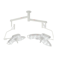
Operating Lights marLEDOperating Lights marLED
®®
E9 / E9i / E15E9 / E9i / E15
V V 1.0 1.0 5353
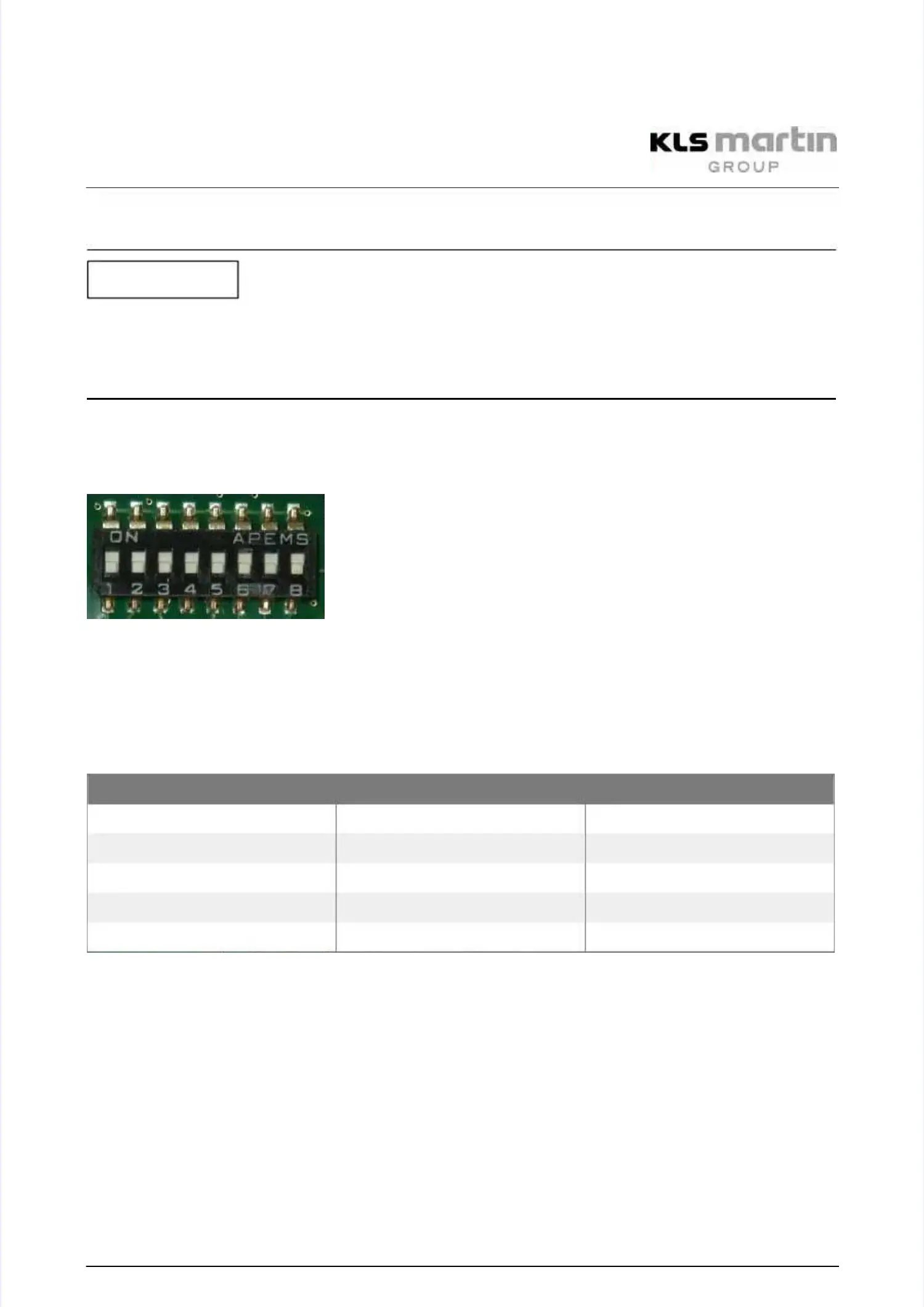
6.176.17 Configuration of the marLEDConfiguration of the marLED
®®
E via DIP SwitchE via DIP Switch
Avoid malfunctions!Avoid malfunctions!
The DIP switch positions must be adopted when replacing the control electronics!The DIP switch positions must be adopted when replacing the control electronics!
DIP switches 3 to 8 must be set to OFF.DIP switches 3 to 8 must be set to OFF.
The light can be configured via a DIP switch on the circuit board.The light can be configured via a DIP switch on the circuit board.
DIP switches for CAN addresses (0 = OFF, 1 = ON) and configuration:DIP switches for CAN addresses (0 = OFF, 1 = ON) and configuration:
DIP switch positions SW 6DIP switch positions SW 6
Upper DIP switch position means ON = 1.Upper DIP switch position means ON = 1.
Lower DIP switch position means OFF = 0.Lower DIP switch position means OFF = 0.
The DIP switch positions must be adopted when replacing the control electronics!The DIP switch positions must be adopted when replacing the control electronics!
Configuration of the CAN-Bus addressesConfiguration of the CAN-Bus addresses
The address (0 to 3) for the CAN-Bus is set via DIP switch.The address (0 to 3) for the CAN-Bus is set via DIP switch.
For the control electronics of the light, these are switches DIP 1 and DIP 2 of SW 6:For the control electronics of the light, these are switches DIP 1 and DIP 2 of SW 6:
SW 6
SW 6 (control electronics)(control electronics)
DIP DIP 1 1 DIP DIP 2 2 CAN-Bus CAN-Bus addressaddress
0 0 00 0 0
1 0 11 0 1
0 1 20 1 2
1 1 31 1 3
DIP 3–DIP 6 are not used.DIP 3–DIP 6 are not used.
For the correct synchronization of several lights, the CAN-Bus address must also be setFor the correct synchronization of several lights, the CAN-Bus address must also be set
correctly without the wall box.correctly without the wall box.
Configuration of the Camera OptionConfiguration of the Camera Option
Switch 7 = ON: If camera is availableSwitch 7 = ON: If camera is available
Configuration between lamp type marLEDConfiguration between lamp type marLED
®®
E15E15
and marLEDand marLED
®®
E9E9
Switch 8 = ON: Controls are configured for lamp type marLED E15Switch 8 = ON: Controls are configured for lamp type marLED E15
®®
..
Switch 8 = OFF: Controls are configured for lamp type marLEDSwitch 8 = OFF: Controls are configured for lamp type marLED
®®
E9.E9.
NOTICENOTICE