Service ManualService Manual
Operating Lights marLEDOperating Lights marLED
®®
E9 / E9i / E9 / E9i / E15E15
18 18 V V 1.01.0
4.3.44.3.4
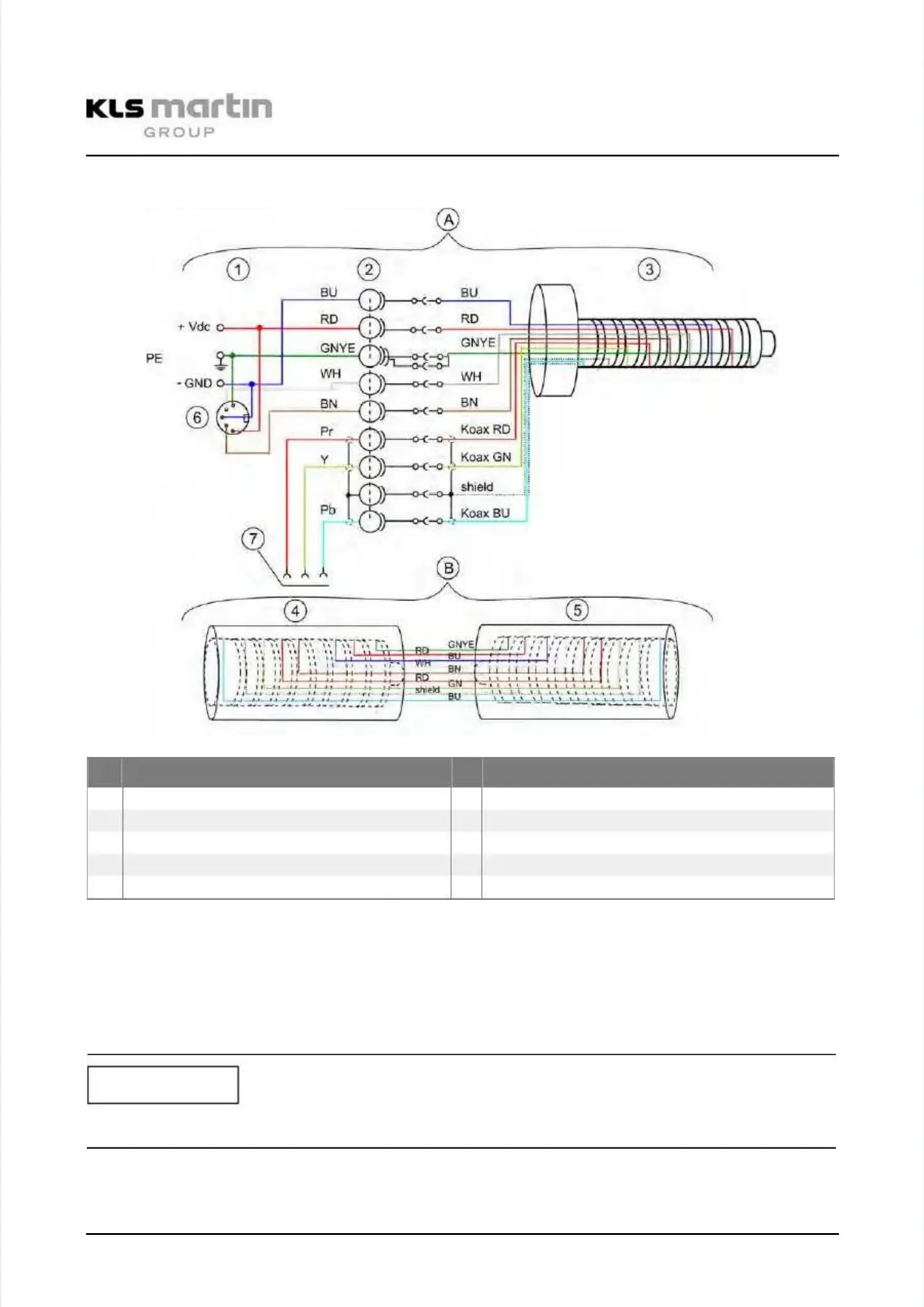
Wiring Diagram 9-pin Cantilever Arm HD Wall Box with optional CameraWiring Diagram 9-pin Cantilever Arm HD Wall Box with optional Camera
A
A Tracking armTracking arm BB Spring armSpring arm
1 1 Plug Plug for for connection connection to to ceiling ceiling tube tube 4 4 Socket Socket to to cantilever cantilever arm arm 9-pin 9-pin HDHD
2 Slip 2 Slip ring ring 9-pole 9-pole HD HD 5 5 Socket Socket to to lamp lamp body body 9-pin 9-pin HDHD
3 3 Plug Plug 9-pole 9-pole HDHD
6 6 DIN DIN socket socket 5-pin 5-pin rear rear viewview
7 7 3x 3x coaxial coaxial socket socket for for Y-Pb-Pr Y-Pb-Pr signalsignal
Color coding for plug connections: Cantilever 1:red, 2:yellow, 3:blue, 4:greenColor coding for plug connections: Cantilever 1:red, 2:yellow, 3:blue, 4:green
Ceiling tube < 400 mm -> DIN socket (6) soldered directly to cableCeiling tube < 400 mm -> DIN socket (6) soldered directly to cable
Ceiling tube > 400 mm -> DIN socket (6) soldered directly to cable, plus 5-pole extensionCeiling tube > 400 mm -> DIN socket (6) soldered directly to cable, plus 5-pole extension
cable (plug / socket)cable (plug / socket)
In multi-light setups, all CAN connecting cables (CAN+ WH, CAN- BN) are parallel-soldered toIn multi-light setups, all CAN connecting cables (CAN+ WH, CAN- BN) are parallel-soldered to
DIN socket (6).DIN socket (6).
When using a combination of lights, please note the different color marks on the connectors.When using a combination of lights, please note the different color marks on the connectors.
Tracking arm 1:Tracking arm 1:
rered d TrTracackiking ng ararm m 3:3: blblueue
Tracking arm 2:Tracking arm 2:
yelyellow low TraTrackicking ng arm arm 4:4: gregreenen
NOTICENOTICE