Service ManualService Manual
Operating Lights marLEDOperating Lights marLED
®®
E9 / E9i / E15E9 / E9i / E15
b) Fixed lightsb) Fixed lights
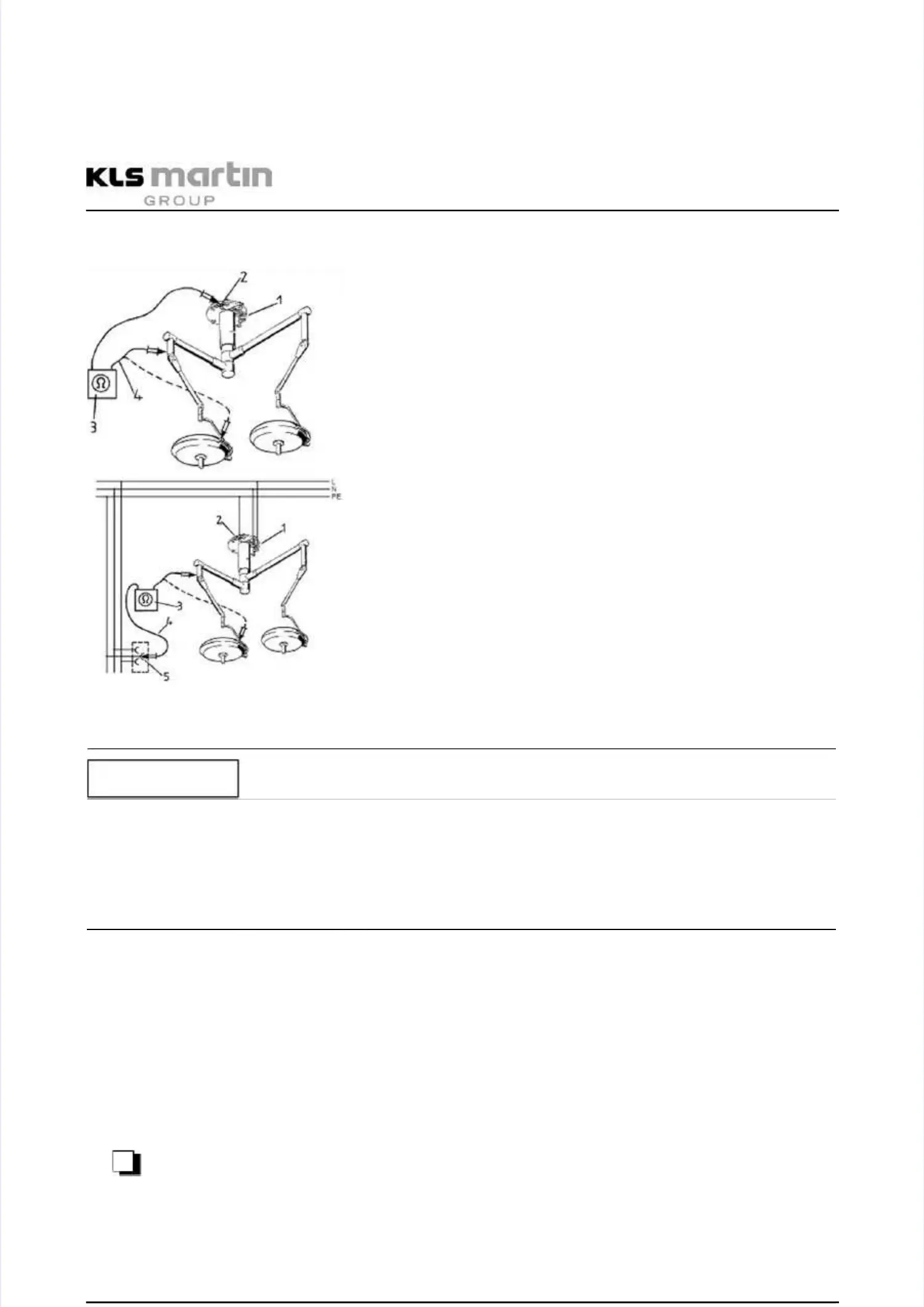
RR
imaximax
= 0.3= 0.3 ΩΩ
1 1 Mains Mains connectionconnection
2 2 Main Main protective protective conductorconductor
terminalterminal
3 3 Measuring Measuring instrumentinstrument
4 4 Measuring Measuring leadsleads
5 5 Externally Externally accessible accessible connectorconnector
Fig. Fig. 10-15 10-15 Resistance Resistance measurement measurement on on non-detachablnon-detachable e lightslights
The external protective conductor may only be used for measurement if the ceiling terminal isThe external protective conductor may only be used for measurement if the ceiling terminal is
no longer accessible after installation (e.g. in the no longer accessible after installation (e.g. in the case of ventilated ceilings). However, thiscase of ventilated ceilings). However, this
requires that both the point 5 and the resistance between points 2 and 5 were documented inrequires that both the point 5 and the resistance between points 2 and 5 were documented in
the initial test report the initial test report (Handover Report) at the time (Handover Report) at the time of installation. This information (“first-of installation. This information (“first-
measured values”) can then be measured values”) can then be used as a reference basis for used as a reference basis for all subsequent measurements.all subsequent measurements.
••
If applicable, measure the resistance between If applicable, measure the resistance between the main protective conductor terminal (2)the main protective conductor terminal (2)
and the nearest protective conductor terminal (5).and the nearest protective conductor terminal (5).
••
Document the location of the external protective conductor (5) and enter the valueDocument the location of the external protective conductor (5) and enter the value
measured between this point and the main protective conductor terminal (2) in the Testmeasured between this point and the main protective conductor terminal (2) in the Test
Report form.Report form.
••
Following installation of the light(s), measure the resistance between point 2 and point 5Following installation of the light(s), measure the resistance between point 2 and point 5
and all metallic parts of the light and enter the highest value obtained in the Test Reportand all metallic parts of the light and enter the highest value obtained in the Test Report
form.form.
••
√√
NOTICENOTICE