enabled, the VAV terminal will be controlled by the DAT loop. The unit will also limit the
Discharge Air Temperature to within 15° F of the Space Temp Reference.
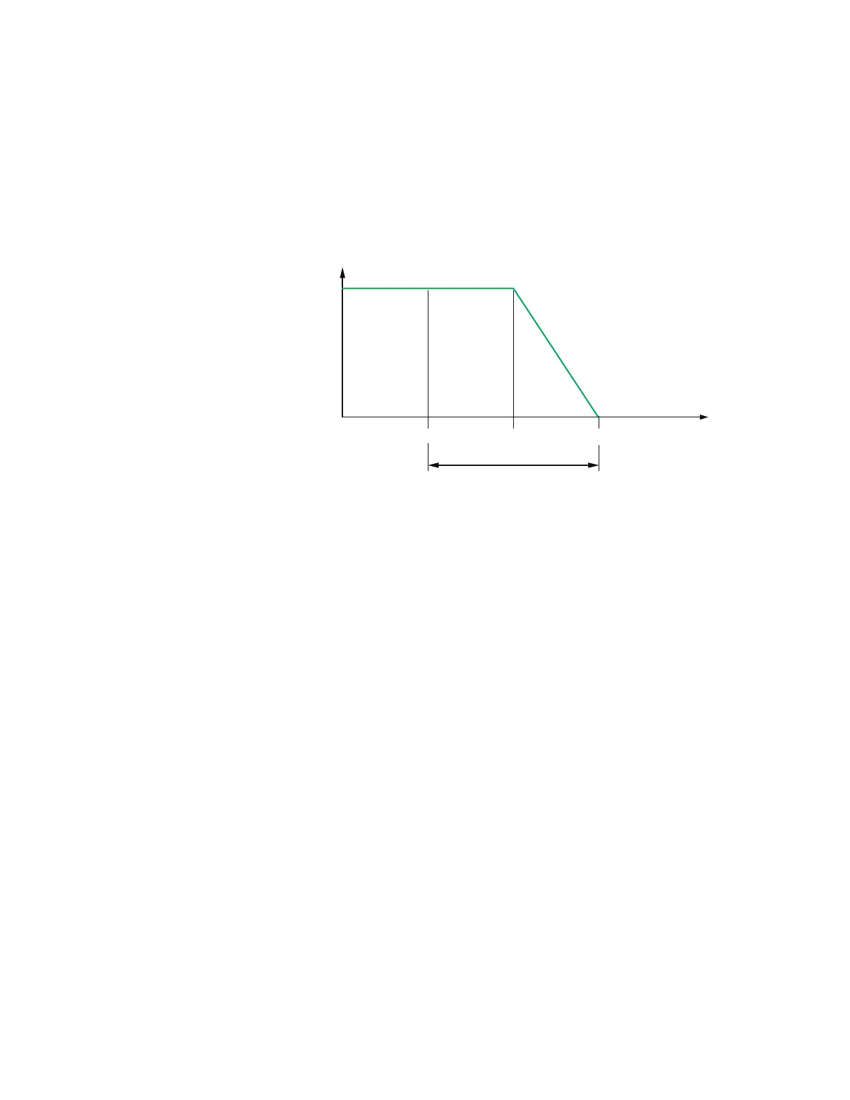
When there is a call for heat and the primary air is cool air, the reheat outputs are directly
controlled by the DAT Loop and the DAT Setpoint reset based on the output of the Heating
loop. As the Heating loop increases from 0% to 50%, DAT Setpoint is proportionally
calculated between Space Temp Reference and Space Temp Reference + 15° F up to
maximum 90° F. This allows the reheat to be controlled by the DAT loop over the first 50% of
a call for heating.
Illustration 7–1 DAT limiting operation
HTG SP
HTG SPAN
50%
100%
0%
ROOM TMP
DAT loop
ROOM TMP+
15°
(Max 90°F)
If DAT Limiting is enabled, and a DAT sensor is not connected, the controller will lockout
reheat control only in the cooling mode. The unit will operate this way until a DAT sensor is
detected or until the unit is commanded to control to the Active Heating Setpoint by a
supervisory BMS.
If the unit has detected a DAT sensor and DAT Limiting is not enabled, the unit’s reheat is
controlled by the Heating loop instead of the DAT loop.
See also the topics Changeover on page 53 and Input sources on page 49.
System diagnostic indicators
The controller programming includes four system diagnostic indicators in the form of BACnet
value objects.
l NEED AHU (BV1)
l NEED COLDER SUPPLY (BV2)
l NEED MORE STATIC (BV3)
l NEED HOTTER SUPPLY (BV7)
These diagnostic indicators or flags are monitored by other BACnet devices, such as air
handling units, connected to the same building automation system as the controller. How
the indicators are used is beyond the scope of these instructions.
Section 7: Sequences of operation KMC Controls, Inc.
54 Revision H
 Loading...