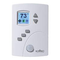
Procedure Detailed steps Sensor display
7 Set the damper direction to
close.
1.
Press the or buttons to which direction to
damper moves to close.
CCW—The actuator turns counterclockwise to close
the damper.
CW—The actuator turns clockwise to close the
damper.
2.
Press the
button to save the damper option and
advance to the next function.
8 Select a new configuration
function or exit.
1.
Press the or buttons to select one of the
following:
l STPT, FLOW, ADVC. or RSTR options
l BACK to choose another configuration function
l EXIT to return to the temperature display.
2.
Press the
button to select the next function.
Procedure to set the box functions (continued)
Set the airflow setpoints
The airflow setpoints set the airflow limits for the VAV terminal unit.
l Airflow heating and cooling minimum and maximum limits
l Auxiliary flow setpoint (optional)
l Minimum and maximum fan speeds (optional)
Setting the airflow setpoints requires entering Password 2 which is described in the topic
Getting started with configuration on page 21.
Note: If the VAV unit is a heat only or cooling only unit, the airflow setpoints for the unused mode
must be set within the range of the mode in use. Failure to set the unused setpoints
correctly will result in unpredictable or erroneous air balancing settings.
Tip: Once the following procedure is started, all steps must be completed in order.
SimplyVAV Section 4: Configuring the controllers
Revision H 29
 Loading...