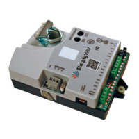
Connect a 10 kΩ, Type 3 thermistor temperature probe to the discharge air temperature
input. The input includes the internal pull-up resistor. An STE-1401 sensor is suitable for this
application. Follow the instructions supplied with the sensor for installation.
l For DAT limiting and reheat, install the sensor in the airflow after the reheat unit. See
the topic, Advanced options on page 33 to enable discharge air temperature control.
l When the DAT sensor is used only to detect primary air temperature, the sensor can be
placed in either location shown in the illustration Discharge air temperature
sensor location.
Illustration 2–6 Discharge air temperature input details
Connecting power
The controllers require a 24 volt, AC power source. Use the following guidelines when
choosing and wiring transformers to the controller.
l Use a Class–2 transformer of the appropriate size to supply power to the controller.
l KMC Controls recommends powering only one controller from each transformer.
l Do not run 24 volt, AC power from within an enclosure to external controllers.
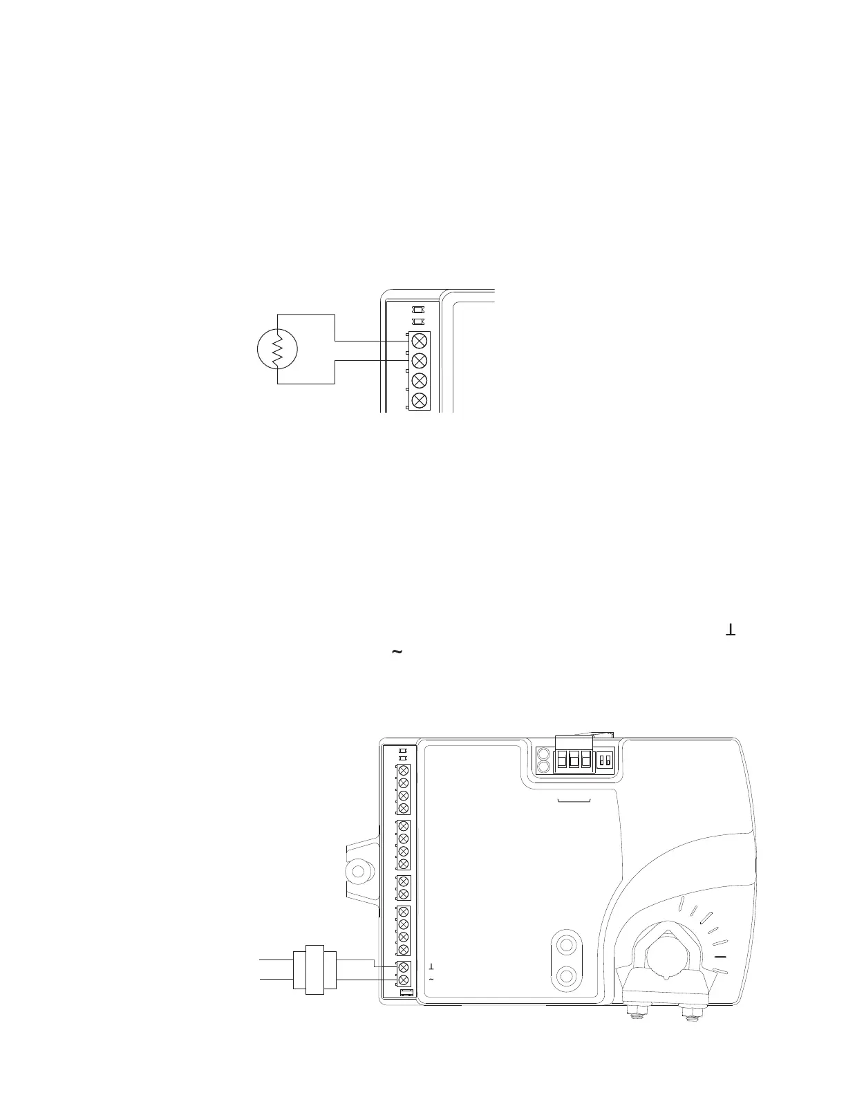
Connect the 24 volt AC power supply to the power terminal block on the lower right side of
the controller. Connect the ground side of the transformer to the ground terminal and the
AC phase to the phase terminal. Power is applied to the controller when the transformer is
connected to power.
Illustration 2–7 Controller power terminals
Blue
Brown
24 VAC
Class 2
ON CTS
1 2
COMM
READY
AI1
AI5
GND
AO4
AO3
SC
BO8
BO5
BO6
SC
BO7
24VAC
AI6
GND
AI7
T-STAT/
SENSOR
-A
+B
S
EOL
BACnet MS/TP
SimplyVAV Section 2: Installing the controllers
Revision H 17
 Loading...