Section 6
Hydraulic System
20425603
5-2005/Rev 0
6-14
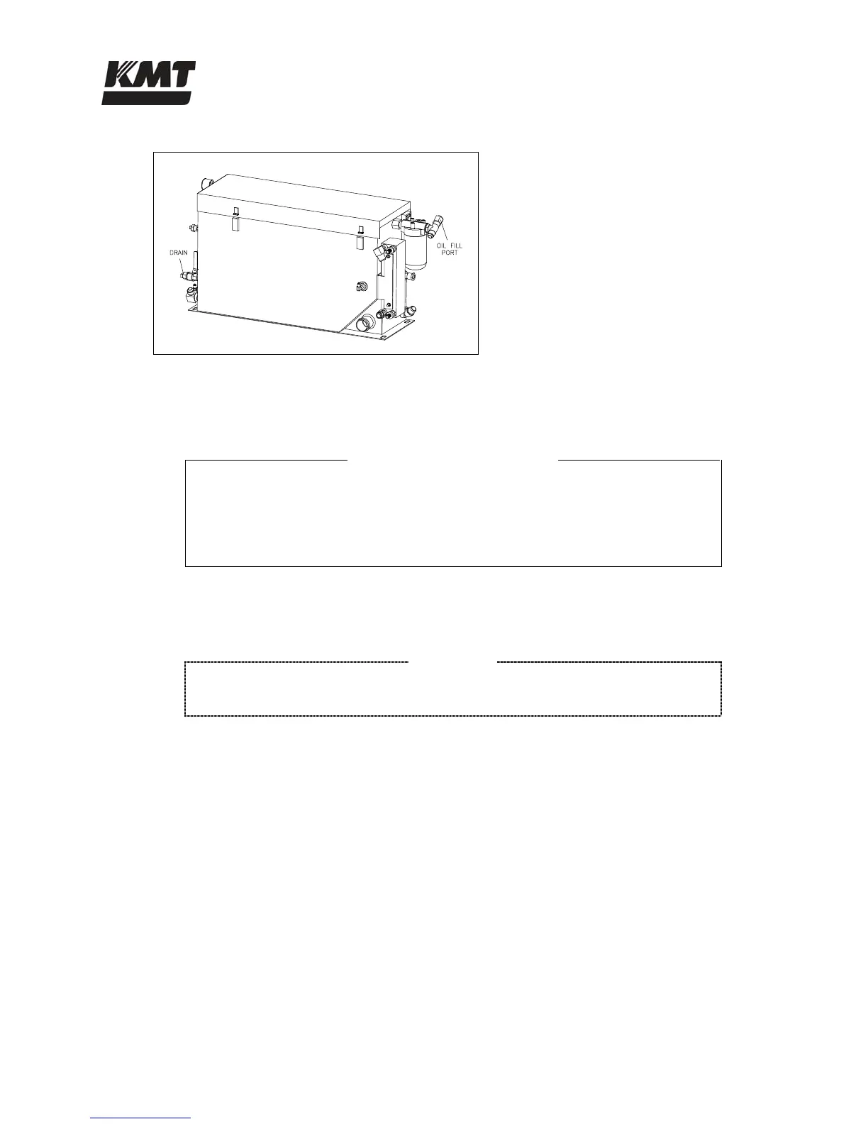
Figure 6-8: Hydraulic Oil Reservoir
3. Disconnect all hydraulic hoses and connections to the case drain, hydraulic pump and
recirculation pump.
REDUNDANT MODELS
Loosen the pressure gauge on the hydraulic manifold and turn it out of the way.
Remove all electrical sensors and connections to the manifold.
Remove the four bolts on the top of the manifold and remove the manifold and o-
ring from the hydraulic pump.
4. Remove the recirculation pump.
NOTE
If the unit is equipped with an optional booster pump, disconnect the water lines
and remove the adapter and the booster pump with the recirculation pump.
5. Remove the bolts that attach the hydraulic pump to the electric motor.
6. Support the pump and slide it away from the motor, disengaging the flexible coupling.
7. Inspect the flexible coupling for damage. If the flexible coupling is damaged it must be
replaced.
8. Inspect the metal splines on the motor coupling half. Wipe any residue, dirt or oil from
the motor coupling and the flexible coupling. Place the flexible coupling on the motor
coupling half, pushing it on as far as it will go.
9. Take a measurement from the front face of the electric motor, the pump mounting
interface, to the outer face of the solid band inside the flexible coupling, dimension A in
Figure 6-9.
 Loading...