Section 2
Installation
20425561
5-2005/Rev 0
2-4
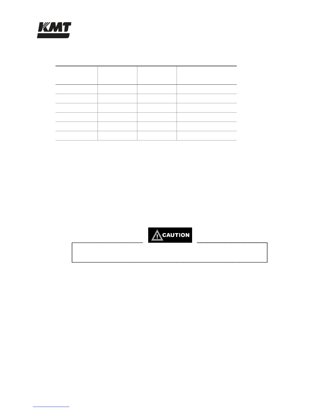
Table 2-2
Ampacity and Power Voltage Requirements
Power Voltage
Motor
Horsepower
Full Load
Amps
Recommended
Circuit Breaker Amps
208/3/50-60 30 86 125
230/3/60 30 76 100
400/3/50 30 43 60
415/3/50 30 43 60
460/3/60 30 38 50
575/3/60 30 32 40
2.5 Service Connections
The intensifier requires two incoming water sources, cooling water and cutting water; a drain line
for cooling water and a high pressure discharge line. A drain line for wastewater is required for
units equipped with an optional dump valve or booster pump. The optional dump valve also
requires an air supply line. All piping must comply with local, regional and national codes.
With the exception of the wastewater drain line, manual shutoff valves should be installed for all
connections. To facilitate service, the valves should be located as close as practical to the
interface connection.
Thoroughly purge all supply plumbing prior to connection to remove any residue
that could contaminate the system.
 Loading...