Section 2
Installation
20425561
5-2005/Rev 0
2-5
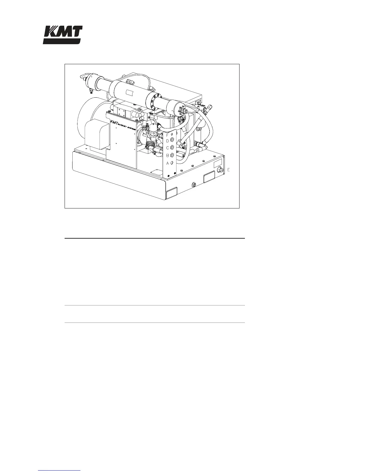
Figure 2-3: Service Connections
Table 2-3
Service Connections
A Drain, optional* 1/2” NPT Connection
B Cutting Water In 1/2” NPT Connection
C Cooling Water Out 1/2” NPT Connection
D Cooling Water In 1/2” NPT Connection
E Cutting Water Out 9/16” HP Connection
F Plant Air, optional** 1/4” NPT Connection
* Supplied with optional booster pump or dump valve
** Supplied with optional dump valve
Cooling Water
Inlet cooling water flows through the oil-to-water heat exchanger in the hydraulic system to
control heat buildup in the hydraulic oil. The cooling water is then discharged through the
cooling water out port to either the drain or routed to a customer supplied water chiller.
Cooling water supply piping must be sized to meet the flow and pressure requirements of the
equipment. If municipal or well water is used for cooling, ensure the supply flow and pressure
meet the requirements in Section 10, Specifications.
 Loading...