Section 8
High Pressure Water System
20425618
5-2005/Rev 0
8-37
21. Apply anti-seize compound to the threads on the 3/8-inch high pressure gland fitting.
Install the collar and the gland fitting and torque to 50 ft-lbs (68 Nm).
22. Install the air supply hose and the electrical connection to the solenoid valve. Turn the air
pressure to the actuator on and test the valve for leaks and proper operation.
Pneumatic Actuator
The following procedure is used to service the pneumatic actuator.
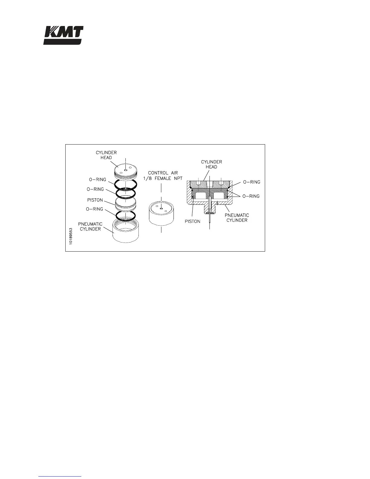
Figure 8-26: Pneumatic Actuator
1. Unscrew and remove the cylinder head. Remove the piston from the cylinder.
2. Remove the o-ring on the cylinder head. Apply FML-2 grease to a new o-ring and install.
3. Remove the two o-rings on the piston. Apply FML-2 grease to two new o-rings and
install.
4. Install the piston in the pneumatic cylinder. Apply anti-seize compound to the threads on
the cylinder head and screw it into the pneumatic cylinder.
 Loading...