Section 8
High Pressure Water System
20425618
5-2005/Rev 0
8-36
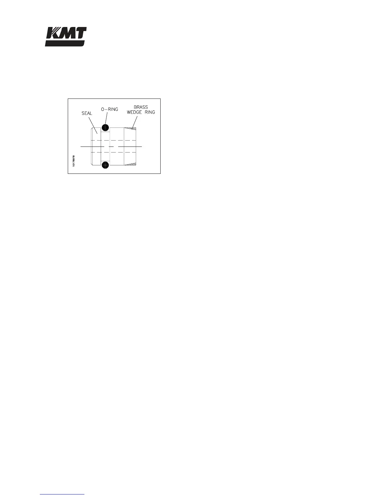
10. To replace the seal assembly, first remove the brass wedge ring. Lubricate a new seal and
o-ring with FML-2 food grade grease. Insert the seal and o-ring into the seal installation
tool, inserting the tapered end of the seal first.
Figure 8-25: Seal Assembly
11. Place the seal positioning tool into the opposite end of the valve body, using the high
pressure adapter to hold the positioning tool.
12. With the seal in position, place the seal installation tool into the mating cavity of the valve
body. Hold the positioning tool in place and use the seal push tool to push the seal into
the bore of the valve body until the shoulder of the push tool contacts the seal installation
tool.
13. Remove the push tool, installation tool and positioning tool.
14. Place the brass wedge ring, thick end first, onto the seal push tool and use it as a guide to
position the wedge ring onto the seal. Remove the push tool and ease the wedge ring
lightly onto the seal with the tip of your finger.
15. Install the existing SST backup ring and a new brass backup ring on a new stem. The vee
groove on the SST backup ring should face toward the brass backup ring. The small OD
of the brass backup ring should face toward the seal assembly. See Figure 8-23,
Pneumatic Control Valve Components.
16. Insert the assembly into the top of the valve body so the stem enters the ID of the seal
assembly.
17. Apply anti-seize compound to the threads of the actuator and carefully thread it into the
valve body, guiding the stem head into the hole in the actuator. Turn the actuator
clockwise until resistance is felt. Reverse the actuator 1/4 turn, and give it a quick spin
clockwise to seat it. Hand tighten only, 5 ft-lbs (7 Nm).
18. Apply anti-seize compound to all surfaces, except the ID, of a new valve seat. Install the
seat into the valve body, inserting the small OD first.
19. Apply anti-seize compound to the threads on the high pressure adapter, and on the back
side of the adapter cone. Position the adapter cone in the adapter, install the adapter and
torque to 50 ft-lbs (68 Nm).
20. Replace the 1/4-inch drain gland nut and collar and torque to 25 ft-lbs (34 Nm).
 Loading...