Section 2
Installation
20425561
5-2005/Rev 0
2-9
Measurements and Dimensions
Tubing must be cut to the proper length, both ends of the tubing must then be coned, threaded and
deburred.
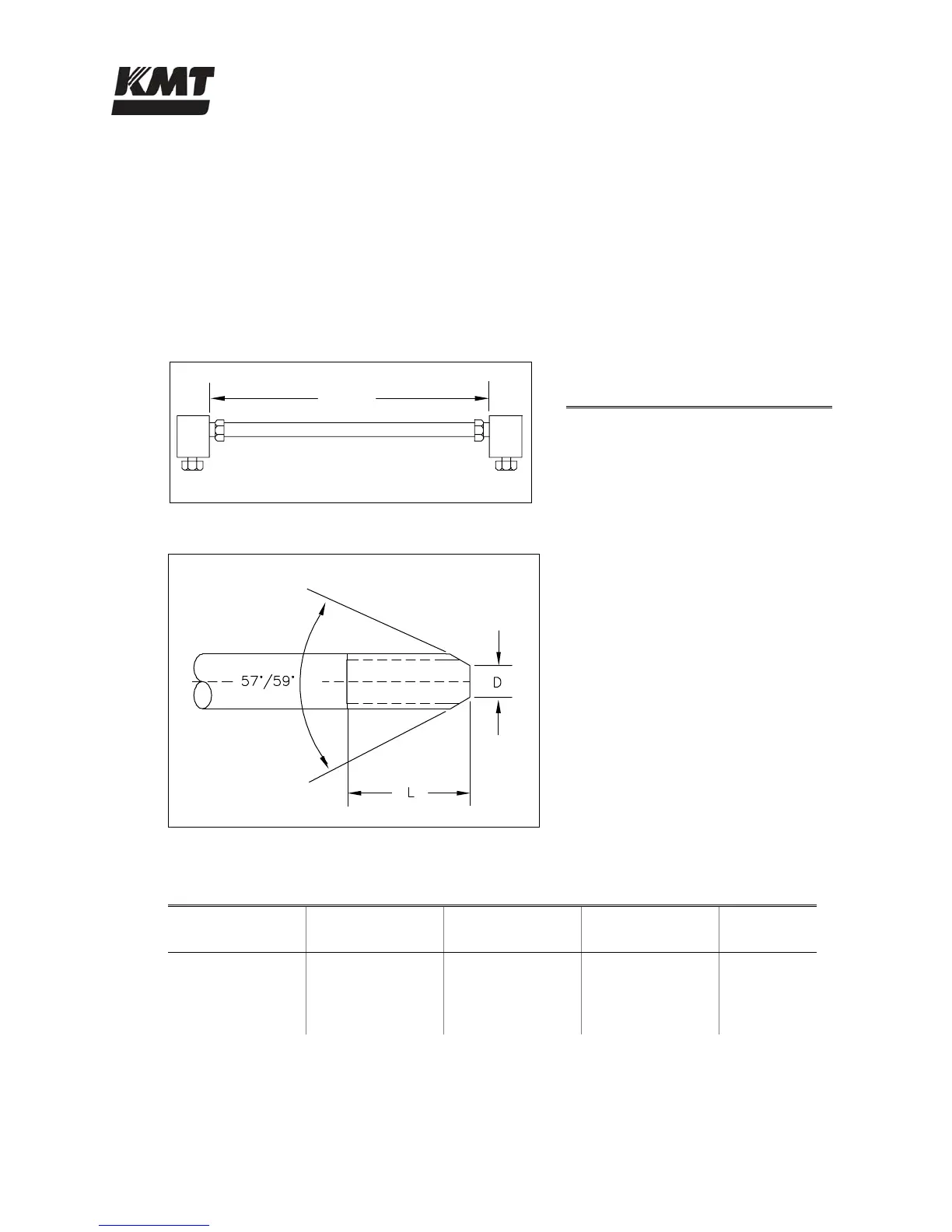
To determine the tube length, measure the distance between the fittings, and add two times the
engagement allowance shown in Table 2-5. Table 2-6 lists the required cone and thread
dimensions illustrated in Figure 2-6.
Figure 2-5: Tube Length
Table 2-5
Engagement Allowance (EA)
1/4” Tubing 0.49” (12.4 mm)
3/8” Tubing 0.68” (17.3 mm)
9/16” Tubing 0.86” (21.8 mm)
Figure 2-6: Cone and Thread Dimensions
Table 2-6
Cone and Thread Dimensions
Tube OD
Tube ID
D
(Maximum)
L
(Maximum)
Thread
UNF-LH
1/4” (6.35 mm) 0.083” (2.11 mm) 0.125” (3.2 mm) 0.562” (14.3 mm) 1/4” - 28
3/8” (9.52 mm) 0.125” (3.18 mm 0.219” (5.6 mm) 0.750” (19.1 mm) 3/8” - 24
9/16” (14.29 mm) 0.188” (4.78 mm) 0.281” (7.1 mm) 0.938” (23.8 mm) 9/16” - 18
TUBE LENGTH = LENGTH + 2(EA)
LENGTH
 Loading...