Section 7
Electrical System
20425610
5-2005/Rev 0
7-3
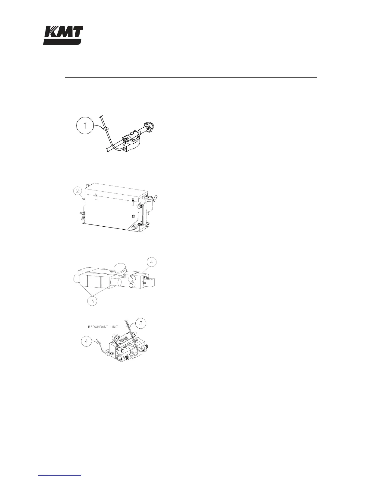
Table 7-2
Sensors and Solenoids
Component
Function
Inlet Water Solenoid Valve
1 The normally closed, inlet water solenoid valve is
located at the service bulkhead. When the control
power is turned on, the valve opens and allows
low pressure cutting water to enter.
Hydraulic Reservoir
2 The temperature/low level switch monitors the oil
temperature and level in the reservoir. Although
the float switch and the temperature switch are
combined in a single unit, the two switches
function independently.
Hydraulic Manifold
3 The 4-way directional control valve shifts the
hydraulics back and forth to the intensifier. A
shift valve directs pressurized oil to one end of
the hydraulic cylinder and returns fluid to the
reservoir from the opposite end, causing the
intensifier to stroke. The movement is controlled
hydraulically by a pilot valve that is
electronically operated by two solenoids. As
power is directed from one solenoid to the other,
LEDs are alternately illuminated.
4 When low pressure is selected, a normally closed,
solenoid valve is activated. The valve remains
closed while operating in high pressure and is
held open electrically during low pressure
operation. An illuminated LED on the solenoid
indicates low pressure operation.
 Loading...