Installing the Cephalostat Unit
5–8 INSTALLING THE CEPHALOSTAT
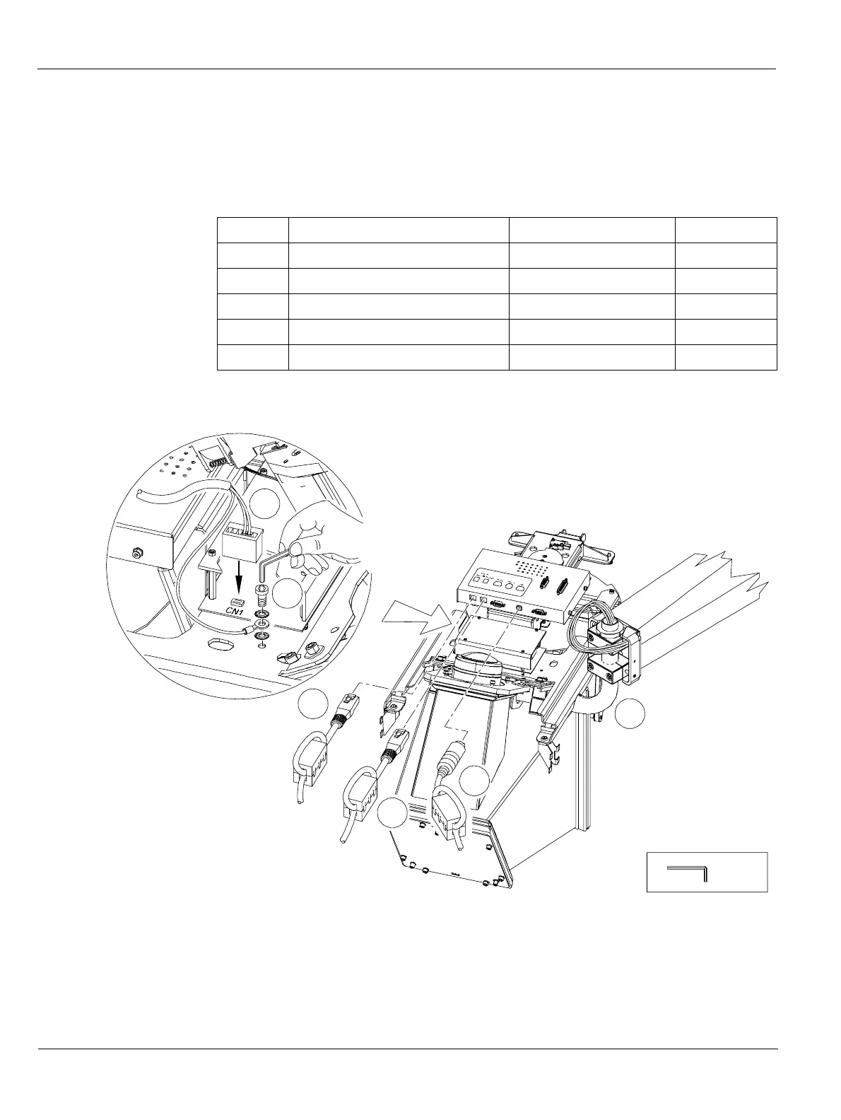
Wiring the Cephalostat Head
9. Pull the cables out of the elbow tube (A). Remove the adhesive tape. Connect the
following wiring in the following order:
Cable ... On the ... To ...
(B) 967/Alim Lambda/CN1 Power supply board CN1
(C) Green and yellow cable Next to power supply box Ground screw
(D) Ethernet Pano (with ferrite) Control box Pano
(E) Ethernet Workstation (with ferrite) Control box Workstation
(F) A14/CJ802/J5 (with ferrite) Control box Synchro
2.5 mm
B
D
A
E
F
C

 Loading...


