System Configuration CVS-128/128B
x 0093112802-06
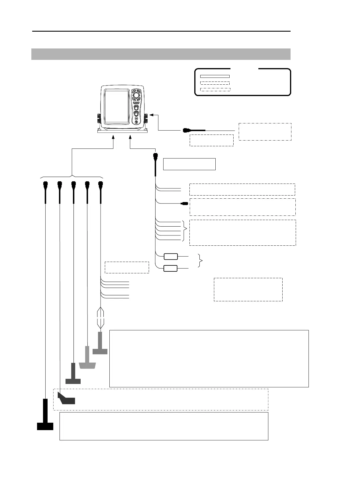
System Configuration
Connection Diagram
CVS-128
Transducer P66 (Dual frequency combination type 50 / 200 kHz)
Plastic made. E
ui
ed with Transom.
Owner su
l
Red
Black
Note: To use the water temperature sensor / speed sensor,
The wiring of transducer connector has to be changed.
Water temperature senso
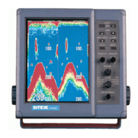
CVS-128/128B Display unit
With mounting bracket and hard cove
External power output (For GPS etc)
External speaker (For speaker with amplifier)
External navigation equipment,
+
-
Connection to the Transduce
Connection to the wate
Connection to the speed sensor
ST-80/90/100
To Transducer connector
To POWER connector
Standard configuration
Option
Owner supply
(J6 connector)
(Owner supply)
To External monitor connector
(J7 connector)
External monitor
CW-576-0.5M
(Owner supply)
CW-264A-2M
10.8 to 31.2VDC
CW-840-0.3M
Legend
external water temperature mete
Temperature
speed senso
NMEA circuit input output
CVS-128
Transducer TD-501C (Dual frequency combination type 50 / 200 kHz)
Rubber mold made. Equipped with Inner-hull/Ship’s bottom/Ship’s side.
Transducer TD-500T-3B / 501T-3B (Dual frequency combination type 50 / 200 kHz)
Bronze made. Equipped with Through-hull.
Transducer TD-500T-2B (Dual frequency combination type 50 / 200 kHz)
Plastic made. E
ui
ed with Inne
-hull.
CVS-128B
Transducer TDM-071 (38 to 75 kHz)
Transducer TDM-091D (42 to 65 kHz) (130 to 210 kHz)
Urethane mold made. Equipped with Ship’s bottom/Ship’s side