5.1 Instrument control
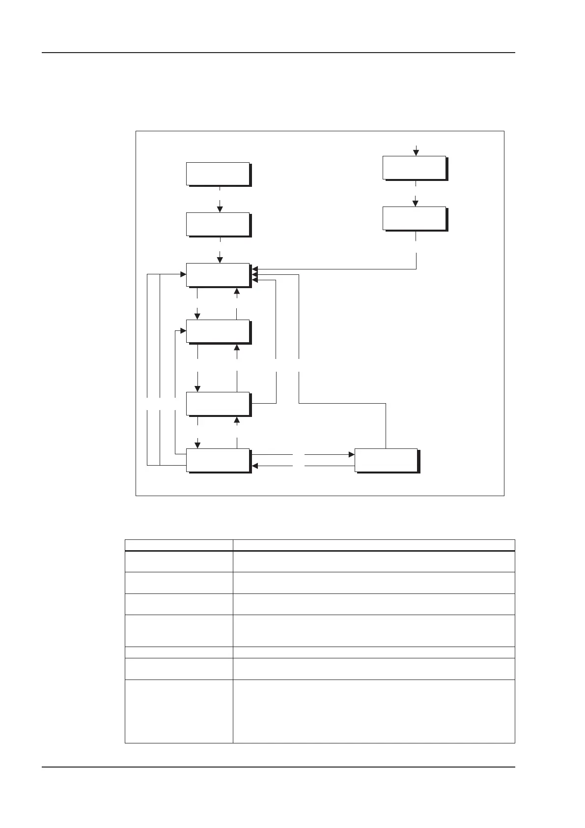
The control of the amplifier through PROFIBUS is described with the aid of the status machine
shown below. The status machine is defined in the drive profile by a flow diagram valid for all oper
-
ating modes. The following diagram shows different amplifier states for the servo amplifier.
The following table describes the amplifier states and the transitions.
States of the status machine
State Description
Not ready for switch-on
servo amplifier is not ready for switch-on. No operation readiness (BTB) is sig
-
naled from the amplifier software.
Switch-on inhibited
servo amplifier is ready for switch-on. Parameters can be transferred, DC bus
link can be switched on, motion functions cannot be carried out yet.
Ready for switch-on
DC bus link voltage must be switched on. Parameters can be transferred,
motion functions cannot be carried out yet.
Ready for operation
DC bus link voltage must have been switched on. Parameters can be trans
-
ferred, motion functions cannot be carried out yet. Output stage is switched on
(enabled).
Operation enabled
No error present. Output stage is switched on, motion functions are enabled.
Fast stop activated
Drive has been stopped, using the emergency stop ramp. Output stage is
switched on (enabled), motion functions are enabled.
Error response active/error
If an amplifier error occurs, the servo amplifier changes to the amplifier state
“Error response active”. In this state, the power stage is switched off
immediately. After this error response has taken place, it changes to the state
“Error”. This state can only be terminated by the bit-command “Error-reset”.
To do this, the cause of the error must have been removed (see ASCII
command ERRCODE).
36 PROFIBUS for S300/S400/S600/S700
Process data channel 04/2017 Kollmorgen
13
14
15
0
1
27
3
6
10
12
8
4
5
11
16
9
17
Output stage
not switched on
Start
Not ready to
switch-on
Switch-on
inhibit
Ready for
switch-on
Ready for
operation
Operation
enabled
Output stage
switched-on
Error response
active
Error
Error
Fast Stop

 Loading...


