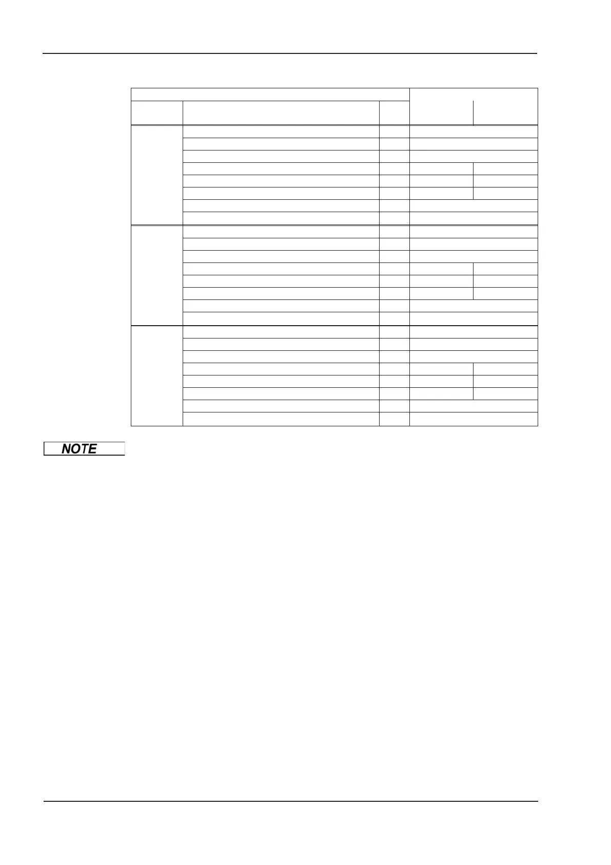
Brake circuit: technical data SERVOSTAR
Supply
voltage
Rated data DIM 601 - 603 606 - 620
3 x 230 V
Upper switch-on level of brake circuit V 400 - 430
Switch-off level of brake circuit V 380 - 410
Overvoltage F02 V 450
Continuous power of brake circuit (R
Bint
) W 80 200
Continuous power of brake circuit (R
Bext
) max. kW 0.25 0.75
Pulse power, internal (R
Bint
max. 1s) kW 2.5 5
Pulse power, external (R
Bext
max. 1s) kW 5
External brake resistor
W
33
3 x 400 V
Upper switch-on level of brake circuit V 720 - 750
Switch-off level of brake circuit V 680 - 710
Overvoltage F02 V 800
Continuous power of brake circuit (R
Bint
) W 80 200
Continuous power of brake circuit (R
Bext
) max. kW 0.4 1.2
Pulse power, internal (R
Bint
max. 1s) kW 8 16
Pulse power, external (R
Bext
max. 1s) kW 16
External brake resistor
W
33
3 x 480 V
Upper switch-on level of brake circuit V 840 - 870
Switch-off level of brake circuit V 800 - 830
Overvoltage F02 V 900
Continuous power of brake circuit (R
Bint
) W 80 200
Continuous power of brake circuit (R
Bext
) max. kW 0.5 1.5
Pulse power, internal (R
Bint
max. 1s) kW 10.5 21
Pulse power, external (R
Bext
max. 1s) kW 21
External brake resistor
W
33
Suitable external brake resistors can be found in our accessories manual.
28 SERVOSTAR
®
601...620 Instructions Manual
Technical description
07/2010 Kollmorgen

 Loading...


