Vers. 062721 70
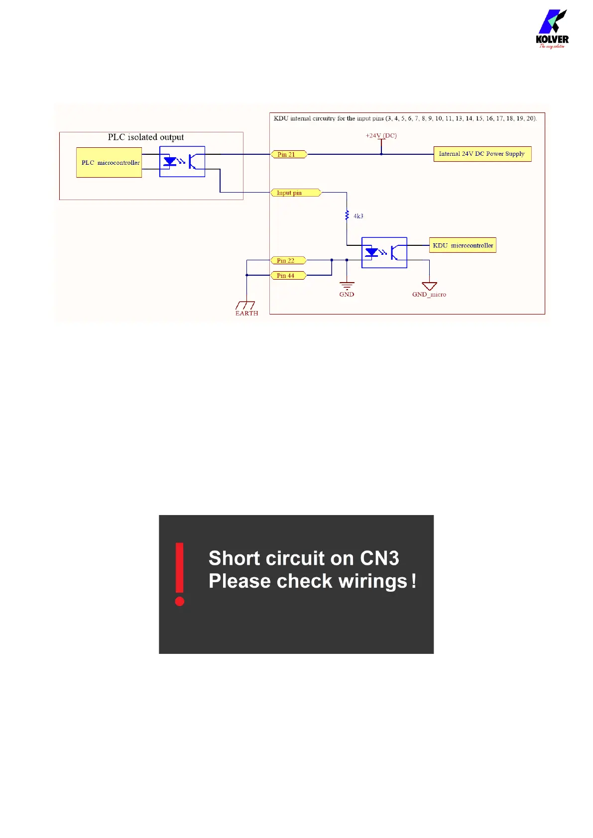
Example on how to enable Input signals using the internal tension on Pin 21:
Outputs (pins 23-43)
When active, an output pin will provide a 24V DC signal on the respective pins with
respect to ground pins 22/44. The signals can be used to activate LEDs / sensors or read
directly from an external PLC. In this case the negative terminal of the KDU unit (pins 22 /
44) must be connected with the negative terminal of the PLC terminal block. The total
power of the output signals is Max 400mA; if exceeded, a protection circuit deactivates the
output signals and activates an alarm on the display (see figure below). The alarm signal
remains active until the power draw drops below the 400mA threshold, which is checked
every 2 seconds.