Vers. 062721 69
Wiring diagrams
Inputs (pins 1-20)
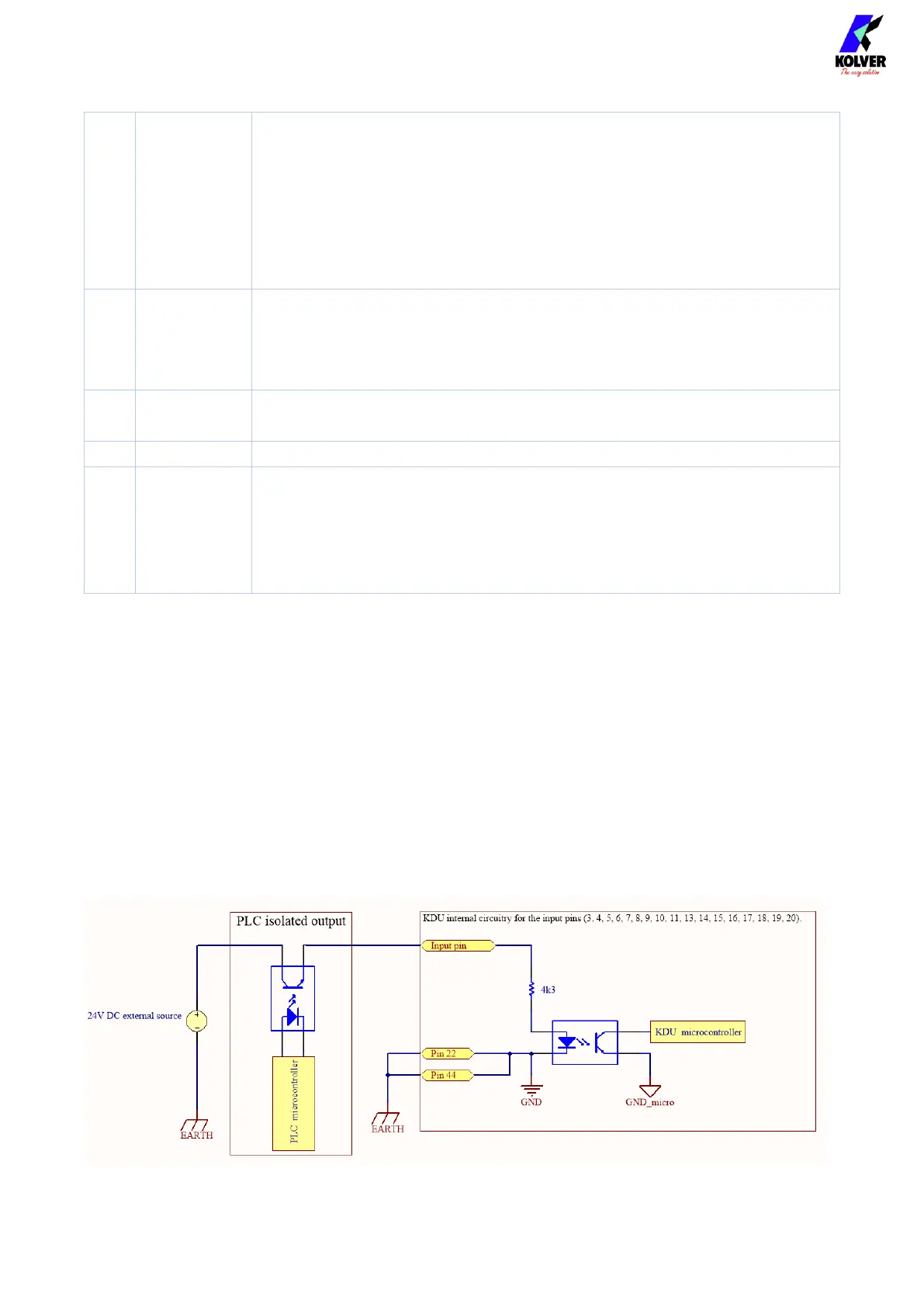
All inputs (Pins 1 to 20) of the CN3 connector require a 24V DC positive signal. The signals
can be powered via an external 24VDC source, in which case the negative terminal of the
source should be connected to pin 22, or via pin 21 (internal 24VDC), in which case the
contact can be controlled with opto-isolator, relay or button to activate the desired input.
Example on how to enable Input signals using an external source:
(Not-OK) This signal activates when the rundown (screw) completes
unsuccessfully, outside of the parameters set for the current
program, for example: torque reached under minimum time, torque
reached outside angle bounds, etc.
This signal remains active until the screwdriver changes state again,
for example, when the operator or the PLC initiates another
rundown.
This signal activates when the rundown (screw) completes
unsuccessfully, outside of the parameters set for the current
program, for example: torque reached under minimum time, torque
reached outside angle bounds, etc.
It activates when the screwdriver motor is running.
It activates when the screwdriver lever is pressed.
Common ground for all inputs and outputs, in parallel with pin 22.
The 24V output signals must be taken between the output pin of
interest and this ground pin.
In a typical PLC input terminal block, the COM(-) pin of the terminal
block should be connected to GND pin 44.