.
ATTACHMENTS AND OPTIONS
MACHINE READY FOR ATTACHMENT
HYDRAULIC CIRCUIT
Hydraulic Circuit Connection
When connecting the attachment, connect the hydraulic circuit as follows.
One Line Attachment
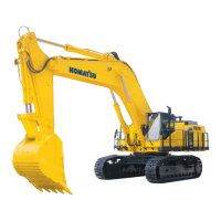
1. Check that the stop valve is at the LOCK position, then remove
the plug.
Be careful not to lose or damage any part that is removed.
2.
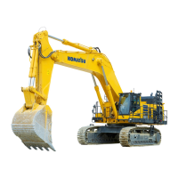
Connect the piping for the attachment provided by the
attachment maker.
The dimensions on the stopper valve side are as indicated at
right. For those on the attachment side, confer with each
manufacturer of attachment and determine.
3.
After connecting the piping, bleed the air from the circuit.
1)
Start the engine, referring to "STARTING ENGINE (PAGE
3-133)", and run it at low idle for the subsequent 10
minutes. Then proceed to the next work.
2)
Run the engine at low idle until the air in the attachment
circuit is completely removed, then operate the attachment
pedal repeatedly (approx. 10 times) to bleed the air.
NOTICE
If the attachment maker specifies an air bleeding procedure for the
attachment itself, follow the specified procedure to bleed the air.
3)
After completing the bleeding of the air, stop the engine, and wait for at least 5 minutes before starting
operations. This will release the bubbles in the oil inside the tank.
4)
Check that there is no oil leakage, and wipe off any oil that has been spilled.
6 - 8