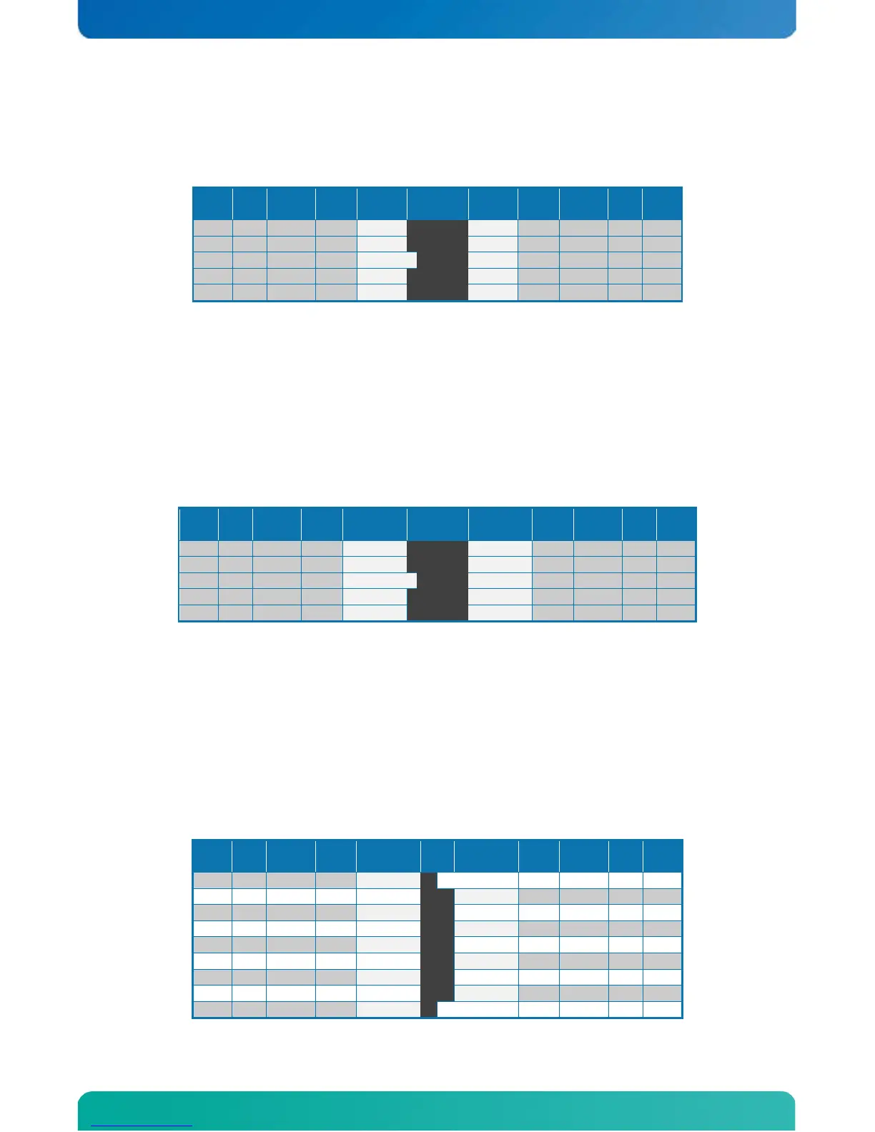
3.8.2 COM2 and COM3 Header Connectors
COM3 is only available on the KTQ45/ATXE.
The pinout of Serial ports COM2 and COM3 is as follows:
Note
Note 1: The COM2 and COM3 5V supply is fused with individual 1.1A resettable fuses for each connector.
A DB9 adapter (ribbon cable) is available for connecting the COM ports to I/O front panel.
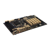
3.8.3 COM4 Header Connectors
COM4 is RS485 (galvanic isolated). COM4 is only available on the KTQ45/ATXE.
The pinout of Serial ports COM4 is as follows:
Note
Note 1: The COM4 header 5V_iso supply is fused with a 1.1A resettable fuse. The power source connected
to this net is delivered by internally galvanic isolated PSU used to power onboard RS485 driver.
The maximum allowed current to drawn on this net must not exceed 50mA if used.
Warning: Do not attempt to connect external power source to this net any attempt might damage the board.
Note 2: RTS signal control the output drivers.
Note 3: 120R termination resistor between signal RxD+ and RxD- is connected on the board.
Note 4: 120R termination resistor between signal TxD+ and TxD- is connected on the board.
Note 5: RxD and TxD pairs can be connected to each other for 2 wire / Half-Duplex transmission line. This
can be configured on the board by adding Jumper JP7 and JP9. The transmitter termination resistor can be
disabled by removing Jumper JP8.
If using Kontron PN 821016 or PN 821017 as DB9 adapter (ribbon cable) then the pinout is as follows:
Note