KTD-00782-H KTQ45 family Page 48 of 92
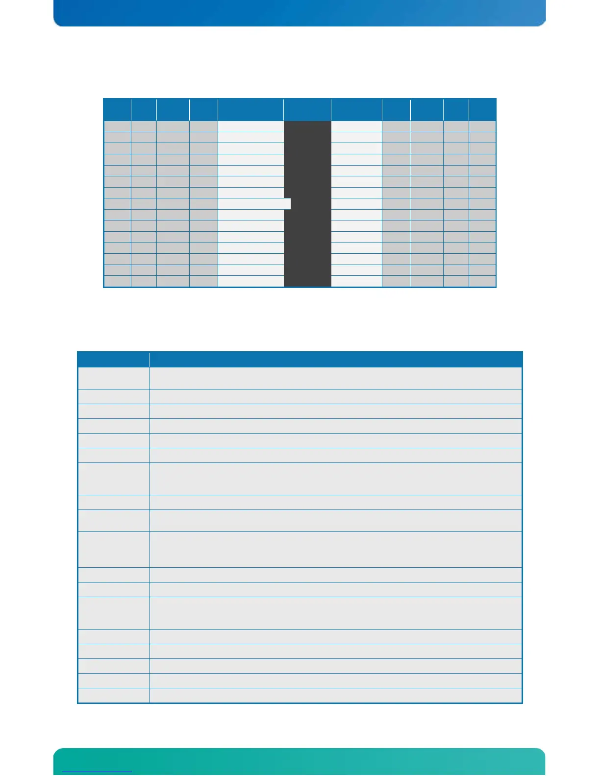
3.20 Feature Connector (FEATURE)
Note
Type Signal PIN Signal Type
Notes:
1. Pull-up to +3V3Dual (+3V3 or SB3V3).
2. Pull-up to onboard Battery.
3. Pull-up to +3V3.
Signal Description
INTRUDER#
INTRUDER, may be used to detect if the system case has been opened. This signal’s
status is readable, so it may be used like a GPI when the Intruder switch is not required.
EXT_ISAIRQ#
EXTernal ISA IRQ, (active low input) can activate standard AT-Bus IRQ-interrupt.
EXT_SMI# External SMI, (active low input) signal can activate SMI interrupt.
PWR_OK PoWeR OK, signal is high if no power failures are detected.
SB5V StandBy +5V supply.
SB3V3 Max. load is 0.75A (1.5A < 1 sec.)
EXT_BAT
(EXTernal BATtery) option for connecting + terminal of an external primary cell battery
(2.5 - 4.0 V) ( – terminal connected to GND etc. pin 10). The external battery is protected
against charging and can be used with or without the onboard battery installed.
+5V Max. load is 0.75A (1.5A < 1 sec.)
GPIO0..7
General Purpose Inputs / Output. These Signals may be controlled or monitored through
the use of the KT-API-V2 (Application Programming Interface).
FAN3OUT
FAN 3 speed control OUTput. This 3.3V PWM signal can be used as Fan control voltage
(0–3.3V DC in 128 steps) via a Fan Driver Circuit (not included) to program Fan voltage.
For more info, see W83627 datasheet. Default PMW output is 127 (100% = 3.3V).
FAN3IN FAN3 Input. 0V to +3V3 amplitude Fan 3 tachometer input.
+12V Max. load is 0.75A (1.5A < 1 sec.)
TEMP3IN
Temperature sensor 3 input. (Recommended: Transistor 2N3904, having emitter
connected to GND (pin 25), collector and basis shorted and connected to pin 23. Further
a resistor 30K/1% shall be connected between pin 23 - 24. (Precision +/- 3ºC).
VREF Voltage REFerence, reference voltage to be used with TEMP3IN input.
IRRX IR Receive input (IrDA 1.0, SIR up to 1.152K bps)
IRTX IR Transmit output (IrDA 1.0, SIR up to 1.152K bps)
SMBC SMBus Clock signal
SMBD SMBus Data signal