19
取扱説明書
Owner’s Manual
Manuel d’utilisation
Bedienungsanleitung
Manual de usuario
EFGSJ 1
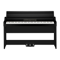
Thank you for purchasing the
Korg G1/G1 Air digital piano.
Merci d’avoir choisi la piano
numérique G1/G1 Air de Korg.
Vielen Dank, dass Sie sich für einen G1/G1 Air
digtal-Klavier von Korg entschieden haben.
このたびは、コルグデジタル・ピアノ G1/G1Air を
お買い上げいただきまして、まことにありがとうございます。
Gracias por comprar el
Korg G1/G1 Air Piano digital.
7. Align the bracket holes in the left and right side panels
with the holes in the speaker box, and then secure them
with the four screws (M4) so the gaps on the left and
right sides are equal.
At the same time, secure the cord holder with the top screw
on the left side panel.
Screws (M4)
Screws (M4)
Cord
holder
8. Connect the aached pedal cord, observing the correct
orientation, to the connector on the reverse side of the
pedal unit, and then engage it with a slot in the pedal
unit.
Thepedal cord can beaached to or detached from the
connector with its locking tab held down.
Locking
tab
9. Lift up either the left or right side of the stand to insert
the pedal unit into the pedal board.
Front
Rear of pedal board
Rear
Push
10. Insert the pedal unit into the pedal board, and then fas-
ten it by pressing a push rivet into the hole (above the
cutout) at the rear of the pedal board.
After installation, lift the stand to check that the pedal unit
does not fall out.
The push rivet will prevent the pedal unit from falling out.
Therefore, it cannot be fully fastened to the pedal board.
11. Firmly tighten the pedal board screws temporarily tight-
ened in step 4.
When tightening the screws on the G1/G1 Air, adjust the
up/down and front/rear positions on the left and right side
panels so that they are equal.
12. Make sure to aach the anti-tipping brackets behind
both side panels. And the anti-tipping bracket fastened
to the left of the code holder at this time.
Aachtheanti-tippingbrackets,startingwiththeround
holeattheboom.
Joints betweenthesidepanels andtheaachedanti-tip-
pingbracketsshouldbeeven(withnoleveldierenceleft).
ネジ(M4)
Screws (M4)
Reverse
Reverse
Cord holder
Anti-tipping
Bracket
Screws (M4)
13. Ensure that the stand has no gaps and is not tilted, and
that all the screws are tightened rmly.
14. Connect the AC adapter (refer to “Connecting the Pow-
er” on page 5), pedal cord and the speaker cord to the
Connector Panel at the center of the underside of the key-
board unit.
When connecting the pedal cord and the speaker cord, ob-
serve the correct orientations of the connectors.
The pedal cord or the speaker cord can be detached from the
connector with its locking tab held down.
Cord
holder
Speaker cord
Pedal cord
Locking tab
15. Use the two cord holders to secure the AC adapter cord
and pedal cord.
After securing the cord with the cord holder, ensure that
excess pressure is not applied to the connectors.
16. Place the G1/G1 Air where you intend to use it. Make
sure to place it in a safe location where the oor is at
and stable.
When seing the digital piano in place, make sure
that the stand does not rest on the AC adapter cord or
pedal cord.
For greater safety, besure to aachthe anti-tipping
brackets to the rear of the left and right side panels.
Check following assembly
□ Are any parts left over?
If any parts are left over, carefully review the assembly
procedure to see where those parts should have been used.
□ Makesurethatallscrewsaretight.

 Loading...