Initial operation 6
Setting the coupling rod 6.3
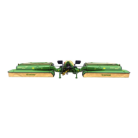
EasyCut B 970
Original Operating Instructions 150000711_01_en 41
Category III (cat. III)
Insert the top link pin (1) in the position (I) or (II) and through the ball sleeve cat. III (2).
The thinner journal of the top link pin (1) is facing outwards.
Secure the top link pin with the linch pin (3).
Make sure that the anti-twist lock (4) of the top link pin is in the recess.
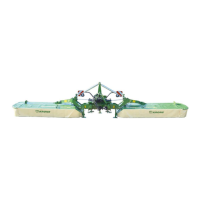
6.3 Setting the coupling rod
KM000-165
ü The machine is connected to the tractor, refer to page43.
ü The machine is in the transport position, refer to page53.
ü The machine is shut down and secured, refer to page24.
Pull the locking pin (1) and move it into position III. Perform the same setting on right-hand
and left-hand machine side.
Ensure that the locking pin (1) moves freely in the oblong hole (III).
Ensure via visual inspection that the locking pin (1) is in the centre of the long hole.
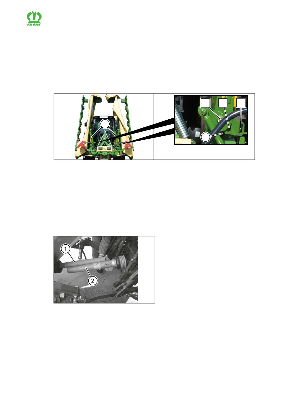
6.4 Adapting universal shaft
KMG000-047
ü The machine is connected to the tractor, refer to page43.
Raise machine until the PTO shaft end of the tractor and the drive shaft of the machine are
on the same height.
Shut down and safeguard the machine, refer to page24.
Disassemble the universal shaft.
Install each half (1, 2) on the tractor and machine side respectively.
Shorten section tubes and guard tubes.