L’apparecchio deve essere posizionato in piano agendo sui quattro piedini regolabili (fig. 6).
Se la lavastoviglie viene incassata, i pannelli laterali e lo schienale possono aderire ai mobili
adiacenti o alle pareti. I tubi di carico e di scarico possono essere orientati verso destra o sinistra
indifferentemente, ma quando l’apparecchio è posizionato i tubi e il cavo elettrico non devono
risultare schiacciati o piegati.
Fig. 6
2.2 Collegamento elettrico
ATTENZIONE!
Il collegamento elettrico deve essere eseguito in conformità alle norme vigenti del paese
nella quale viene installata la macchina.
Prima di collegare la macchina, accertarsi che il voltaggio e la frequenza della rete elettrica
corrispondano a quanto indicato nella targhetta identificativa e che la macchina
sia collegata ad un efficace impianto di messa a terra;
Nella parte posteriore della macchina è presente un morsetto contrassegnato con il simbolo
necessario per il collegamento equipotenziale tra i diversi apparecchi.
La macchina, deve essere protetta a monte, contro sovraccarichi e cortocircuiti da un
interruttore onnipolare di tipo magnetotermico,con adeguatopotere di interruzione, o da un
sezionatore sottocarico e fusibili del tipo gL di adeguata portata.
Contro i contatti indiretti deve essere installato subito a valle dell’interruttore magnetotermico
odel sezionatore/fusibili, un interruttore differenziale con corrente di intervento coordinata
con il valore della resistenza dell’impianto di terra dell’utente.
Il cavo di alimentazione, fornito con la macchina, è del tipo H07RN-F.
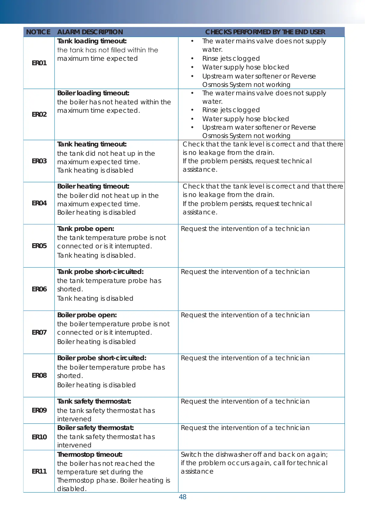
NOTICE ALARM DESCRIPTION CHECKS PERFORMED BY THE END USER
ER01
Tank loading timeout:
the tank has not lled within the
maximum time expected
• The water mains valve does not supply
water.
• Rinse jets clogged
• Water supply hose blocked
• Upstream water softener or Reverse
Osmosis System not working
ER02
Boiler loading timeout:
the boiler has not heated within the
maximum time expected.
• The water mains valve does not supply
water.
• Rinse jets clogged
• Water supply hose blocked
• Upstream water softener or Reverse
Osmosis System not working
ER03
Tank heating timeout:
the tank did not heat up in the
maximum expected time.
Tank heating is disabled
Check that the tank level is correct and that there
is no leakage from the drain.
If the problem persists, request technical
assistance.
ER04
Boiler heating timeout:
the boiler did not heat up in the
maximum expected time.
Boiler heating is disabled
Check that the tank level is correct and that there
is no leakage from the drain.
If the problem persists, request technical
assistance.
ER05
Tank probe open:
the tank temperature probe is not
connected or is it interrupted.
Tank heating is disabled.
Request the intervention of a technician
ER06
Tank probe short-circuited:
the tank temperature probe has
shorted.
Tank heating is disabled
Request the intervention of a technician
ER07
Boiler probe open:
the boiler temperature probe is not
connected or is it interrupted.
Boiler heating is disabled
Request the intervention of a technician
ER08
Boiler probe short-circuited:
the boiler temperature probe has
shorted.
Boiler heating is disabled
Request the intervention of a technician
ER09
Tank safety thermostat:
the tank safety thermostat has
intervened
Request the intervention of a technician
ER10
Boiler safety thermostat:
the tank safety thermostat has
intervened
Request the intervention of a technician
ER11
Thermostop timeout:
the boiler has not reached the
temperature set during the
Thermostop phase. Boiler heating is
disabled.
Switch the dishwasher off and back on again;
if the problem occurs again, call for technical
assistance
48