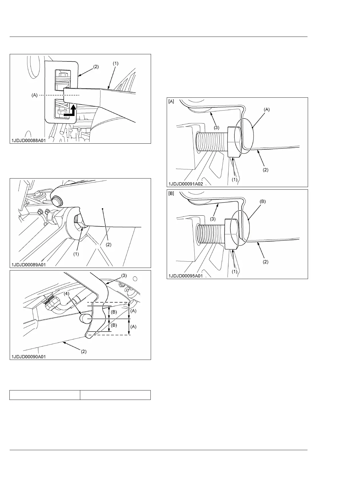
13. Position the stand lever as shown in the figure.
(1) Stand lever
(2) Lever guide
(A)
Center
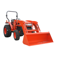
14. T
urn the adjusting bolt on the right side of the
loader to set the stand pin as shown as follows.
(1) Adjusting bolt
(2) Stand
(3)
Stand hook
(4) Stand pin
(A) Almost the same length
(B) Adjusting range
Adjusting range (B) ± 15 mm
IMPORTANT :
• Be careful
not to allow the stands to go
beyond their adjustable range. Otherwise
the stands may get damaged.
15. Lock the stand pin using the lock nut.
16. Turn
the adjusting bolt and lock the stand pin on the
left side of the loader in the same way as for the
right side.
17. Look at the right and left stands to make sure that
the heads of the adjusting bolts are pressed upon
the stands.
(1) Adjusting bolt
(2) Stand
(3)
Link 3
[A] Good
[B] No good
(A) Pressed
(B) Not pressed
IMPORTANT :
• Double-check that the heads of the adjusting
bolts
are pressed upon the stands.
Otherwise the stands may get damaged in
storing them away.
REINSTALLING THE LOADER


 To Next Page