30 / 65 Issued: 29.11.2012 Version: KR C4 Interbus 1.1 V2 en (PDF)
Interbus 1.1
Example INTERBUS master configuration with SVC file:
A bus device has 32 inputs and outputs. The inputs and outputs are found at
a specific address in the SVC file:
32 inputs at byte 10 (master ring)
32 outputs at byte 8 (master ring)
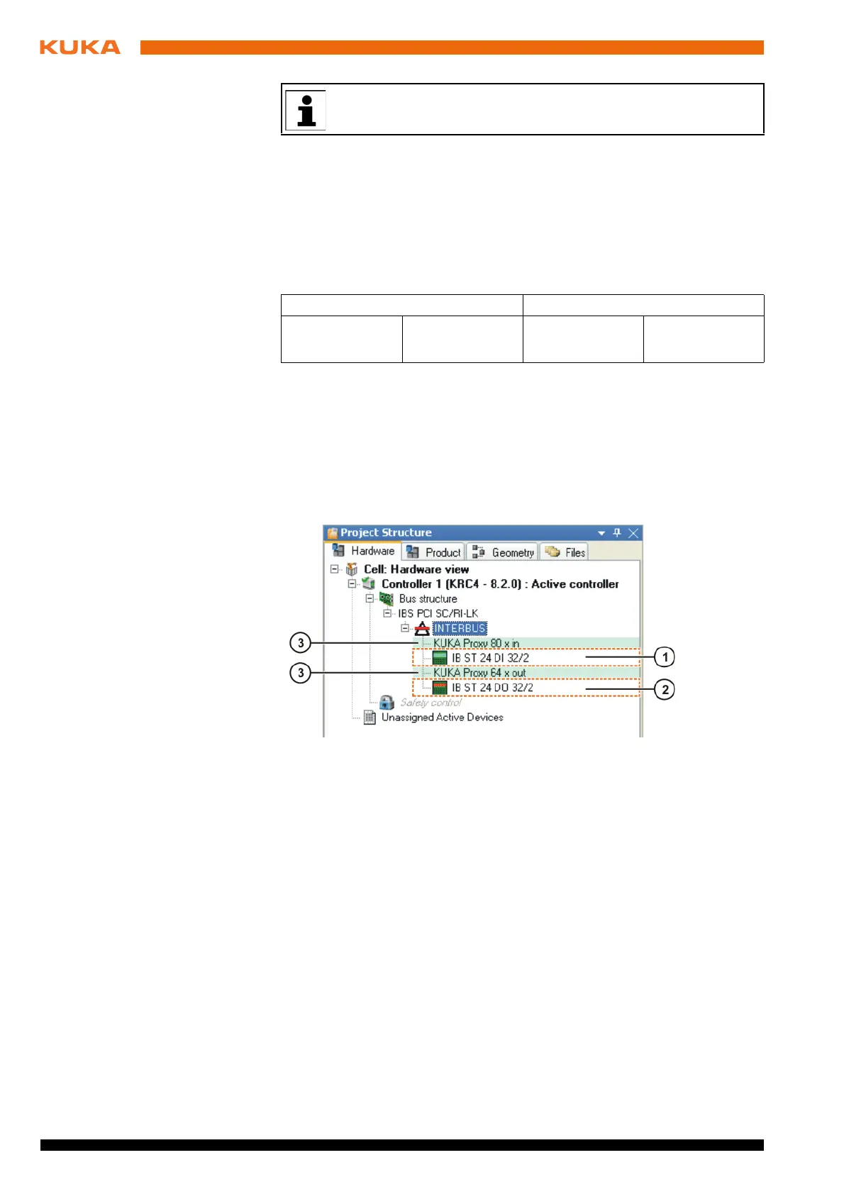
The master card creates the following image:
The image must be replicated in WorkVisual (>>> Fig. 6-4 ).
To ensure that the structure of the Interbus is read correctly, an offset must be
entered so that the precise addresses of the inputs and outputs are located at
the right place in the image (>>> 6.5.5 "Setting an offset" Page 33).
Alternatively, placeholders can be inserted, as shown in the example. All de-
vice description files except “KUKA Slave Proxy” can be used as placeholders
in the master ring.
6.5.3 Configuring the INTERBUS slave
Description The start address and the length of the image of the slave must be set in the
Interbus communication DTM for configuration of the Interbus slave
(>>> 6.4 "Configuring the file IBSPCI.XML" Page 24). Alternatively, the slave
can also be configured with Config+ (SVC file) and the generated SVC file im-
ported in the Interbus communication DTM. The image (bus configuration)
must then be replicated in WorkVisual. The controller is inserted into the bus
just like any other Interbus device.
Precondition
A robot controller has been added and set as active.
Procedure 1. Expand the tree structure of the robot controller on the Hardware tab in
the Project structure window.
2. Right-click on Bus structure and select Add… from the context menu.
The smallest possible memory unit is 2 bytes. A memory of 2 bytes is
created in the image for 8 inputs and/or outputs.
IN OUT
Empty
10 byte
32 inputs Empty
8 byte
32 outputs
Fig. 6-4: Example of an INTERBUS master image
1 32 inputs 3 Placeholders (marked green)
2 32 outputs