40 / 65 Issued: 29.11.2012 Version: KR C4 Interbus 1.1 V2 en (PDF)
Interbus 1.1
The CMD interface is designed as a 6-contact mini-DIN socket (PS/2) on the
front plate .
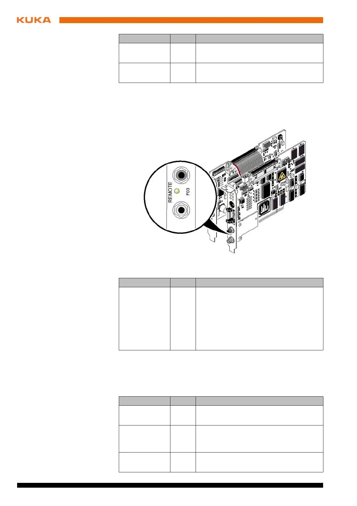
The master module also has an LED FO3 (Fiber Optic 3) for diagnosis of the
outgoing fiber-optic cable.
8.4 LEDs on the slave module
The diagnostic LEDs of the slave module indicate its state and that of the high-
er-level Interbus system:
PF Yellow Peripheral Failure
Periphery fault of a device
BSA Yellow Bus Segment Aborted
One or more bus segments are switched off
Fig. 8-2: LED for diagnosis of the outgoing fiber-optic cable interface
Designation Color Meaning
FO3 Yellow Fiber Optic 3
Lights up when the initialization of the outgo-
ing interface is not OK, or a MAU warning is
present due to poor transmission quality on
the path. This applies to the outgoing data
path/transmitter to the following module; the
state of the return data path/receiver is diag-
nosed by the following module.
Designation Color Meaning
Designation Color Meaning
UL Green U Logic
Operating voltage present
RC Green Remote bus Check
The connection to the higher-level controller
board has been established
BA Flash-
ing
Bus Active
Bus is in the ACTIVE state