22 / 65 Issued: 29.11.2012 Version: KR C4 Interbus 1.1 V2 en (PDF)
Interbus 1.1
to any value between 1 and 8. The default value is 1. It is not necessary to
change the card number if only one Interbus card is used.
4 ... 6: Additions DIP switches 4 to 6 are reserved for expansions and must not be changed.
7: Baud rate DIP switch 7 is used to set the baud rate. The DIP switch is set to OFF by de-
fault, i.e. the baud rate is detected automatically. This setting must not be
changed.
8: Test mode DIP switch 8 is used to activate the test mode. If the system is rebooted with
test mode active, the controller board starts up the Interbus with physical ad-
dressing and activates it. During test mode, the controller board does not re-
spond to instructions from the host system (PC). The controller board
initializes the Interbus system and then starts it up automatically. Outputs are
not set.
6.3 DIP switches on the slave module
The DIP switches are on the top left-hand side of the slave module.
KUKA default: DIP 1 … 4 OFF, DIP 5 ON, DIP 6 … 9 OFF, DIP 10 ON
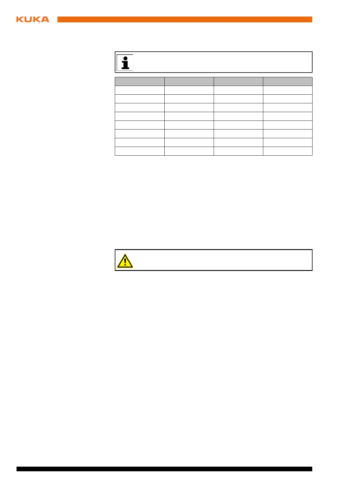
The card number must be specified when the driver is installed. It is
advisable to make a note of it after making the setting.
Card number DIP switch 1 DIP switch 2 DIP switch 3
1 (default) OFF OFF OFF
2ONOFFOFF
3OFFONOFF
4ONONOFF
5OFFOFFON
6ONOFFON
7OFFONON
8ONONON
In normal operation of the controller board, test mode must be deac-
tivated by setting switch 8 to OFF.