23 / 65Issued: 29.11.2012 Version: KR C4 Interbus 1.1 V2 en (PDF)
6 Configuration
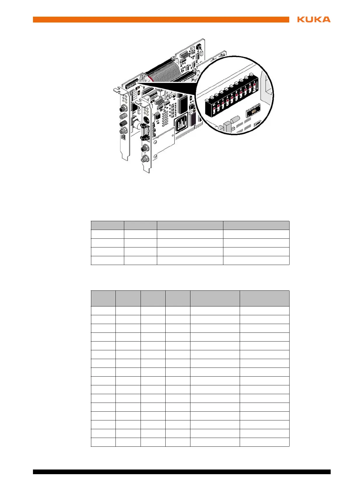
1, 2: Parameter
channel
DIP switches 1 and 2 are used for setting the parameter channel (PCP). This
setting also defines the ID code of the remote interface. The parameter chan-
nel and the process data channel can have a maximum width of 16 words.
3 ... 6: Process
data length
DIP switches 3 to 6 are used for setting the process data length. The length of
the process data also defines the length code.
Fig. 6-2: DIP switches on the slave module
DIP 1 DIP 2 Parameter channel ID code (decimal)
OFF OFF 0 words 3
ON OFF 1 word 235
OFF ON 2 words 232
ON ON 4 words 233
DIP 3 DIP 4 DIP 5 DIP 6 Process data Length code
(decimal)
OFF OFF OFF OFF 0 words 0
ON OFF OFF OFF 1 word 1
OFF ON OFF OFF 2 words 2
ON ON OFF OFF 3 words 3
OFF OFF ON OFF 4 words 4
ON OFF ON OFF 5 words 5
OFF ON ON OFF 6 words 6
ON ON ON OFF 7 words 7
OFF OFF OFF ON 8 words 8
ON OFF OFF ON 9 words 9
OFF ON OFF ON 10 words 10
ON ON OFF ON 11 words 11
OFF OFF ON ON 12 words 12
ON OFF ON ON 13 words 13
OFF ON ON ON 14 words 14
ON ON ON ON 16 words 16