32 / 65 Issued: 29.11.2012 Version: KR C4 Interbus 1.1 V2 en (PDF)
Interbus 1.1
6.5.4 Configuring the INTERBUS master and slave
Description In order to be able to configure the master and slave rings together, an SVC
file must be created with Config+. The image (bus configuration) must then be
replicated in WorkVisual.
Precondition
A robot controller has been added and set as active.
Procedure 1. Expand the tree structure of the robot controller on the Hardware tab in
the Project structure window.
2. Right-click on Bus structure and select Add… from the context menu.
3. A window opens. Depending on which card is used, select the entry IBS
PCI SC/RI-I-T or IBS PCI SC/RI-LK and confirm with OK. The entry is in-
serted in the tree structure.
4. Open the tree structure as far as possible. Right-click on INTERBUS and
select Add… from the context menu. The DTM Selection window is
opened.
5. Select the desired device and confirm with OK. The device is inserted in
the tree structure.
6. If necessary, repeat steps 4 and 5 for further devices.
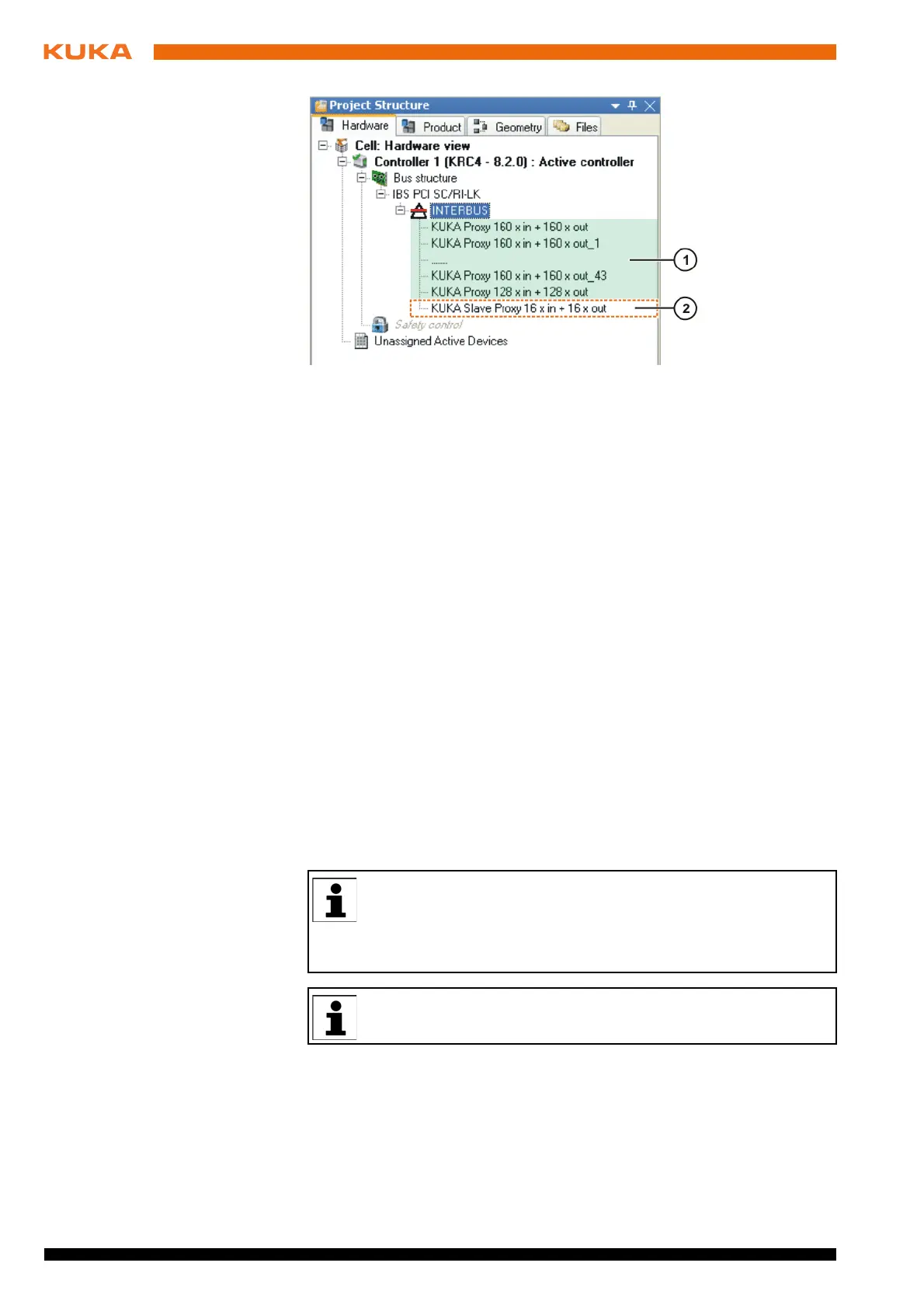
Example INTERBUS master and slave configuration with SVC file:
A bus device has a master ring with 32 inputs and outputs and a slave ring with
16 inputs and outputs. These are found at a specific address:
32 inputs at byte 12 (master ring)
32 outputs at byte 8 (master ring)
16 inputs from byte 896 (slave ring)
Fig. 6-5: Example of an INTERBUS slave image
1 Placeholders (marked green) 2 16 inputs and outputs
The device description files from the manufacturers or the generic de-
vice description files “KUKA Proxy” from KUKA can be used for the
master configuration.
The generic device description files “KUKA Slave Proxy” from KUKA must be
used for the slave configuration.
The smallest possible memory unit is 2 bytes. A memory of 2 bytes is
created in the image for 8 inputs and/or outputs.