21 / 65Issued: 29.11.2012 Version: KR C4 Interbus 1.1 V2 en (PDF)
6 Configuration
6 Configuration
6.1 Overview
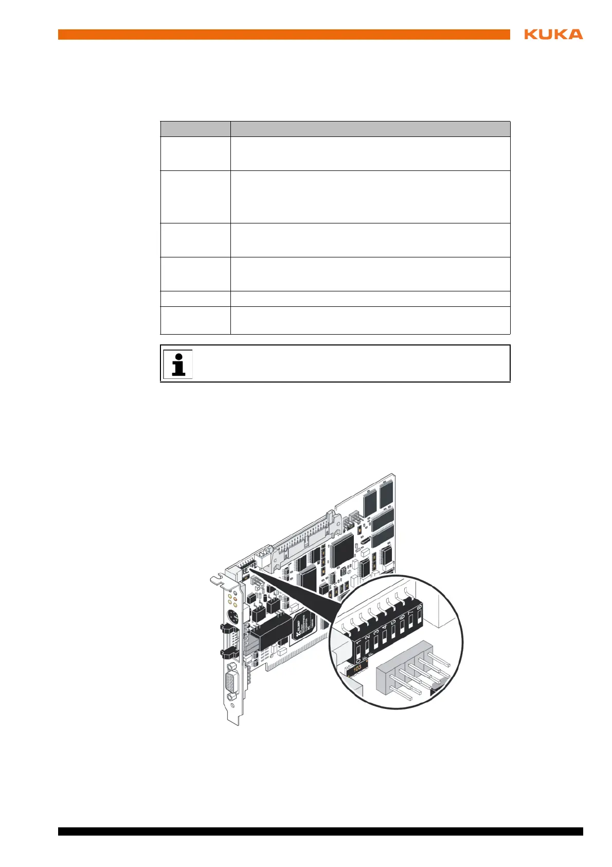
6.2 DIP switches on the master module
The DIP switches are on the top left-hand side of the master module.
KUKA default: DIP 1 … 3 OFF
1 ... 3: Card
number
DIP switches 1 to 3 are used for setting the card number. If multiple Interbus
cards are used, a card number must be assigned to each one. This number is
used to identify the different cards in the system. The card number can be set
Step Description
1 DIP switches of master module
(>>> 6.2 "DIP switches on the master module" Page 21)
2 Only if INTERBUS slave present.
DIP switches of slave module
(>>> 6.3 "DIP switches on the slave module" Page 22)
3 Configure the configuration file IBSPCI.XML.
(>>> 6.4 "Configuring the file IBSPCI.XML" Page 24)
4 Configure INTERBUS with WorkVisual.
(>>> 6.5 "Configuring the bus with WorkVisual" Page 28)
5 Map the inputs and outputs in WorkVisual.
6 Transfer the bus configuration from WorkVisual to the robot
controller.
Additional information about procedures in WorkVisual is contained in
the WorkVisual documentation.
Fig. 6-1: DIP switches on the master module
 Loading...