18 / 65 Issued: 29.11.2012 Version: KR C4 Interbus 1.1 V2 en (PDF)
Interbus 1.1
5.4 IBS PCI SC/RI/I-T
5.5 External power supply to slave
An external 24 V DC power supply is required for operation of the slave mod-
ule. This is connected via a 2-pin MINI-COMBICON connector.
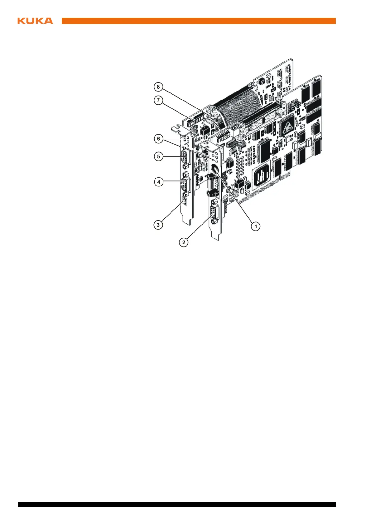
Fig. 5-5: Configuration of the IBS PCI SC/RI/I-T controller board
1 RS232 interface (CMD connection)
2 Master interface (Remote Out, outgoing remote bus)
3 External 24 V supply voltage (slave)
4 Slave interface (Remote Out, outgoing remote bus)
5 Slave interface (Remote In, incoming remote bus)
6 Indicator elements (LEDs)
7 DIP switches for the slave configuration
8 DIP switches for the master configuration