41 / 65Issued: 29.11.2012 Version: KR C4 Interbus 1.1 V2 en (PDF)
8 Diagnosis
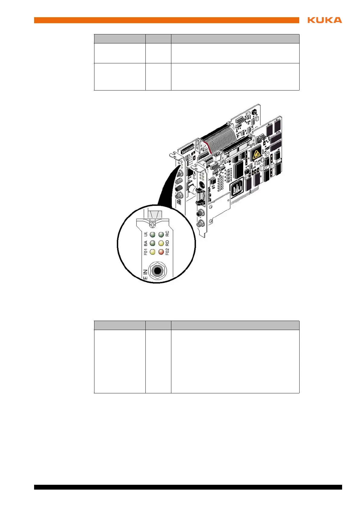
The slave module also has two other LEDs for diagnosis of the fiber-optic ca-
ble:
8.5 IOCTL commands
Description The IOCTL commands are also used for advanced troubleshooting.
Precondition
All communications cables have been installed.
Expert user group
BA Green Bus Running
Bus is in the RUN state
RD Red Remote bus Disabled
The outgoing remote bus interface is deacti-
vated
Fig. 8-3: LEDs on the slave module
Designation Color Meaning
FO1, FO2 Yellow Fiber Optic 1, Fiber Optic 2
Light up when the initialization of the outgoing
interface is not OK, or a MAU warning is
present due to poor transmission quality on
the path. This applies to the outgoing data
path/transmitter to the following module; the
state of the return data path/receiver is diag-
nosed by the following module.
Designation Color Meaning