24 / 65 Issued: 29.11.2012 Version: KR C4 Interbus 1.1 V2 en (PDF)
Interbus 1.1
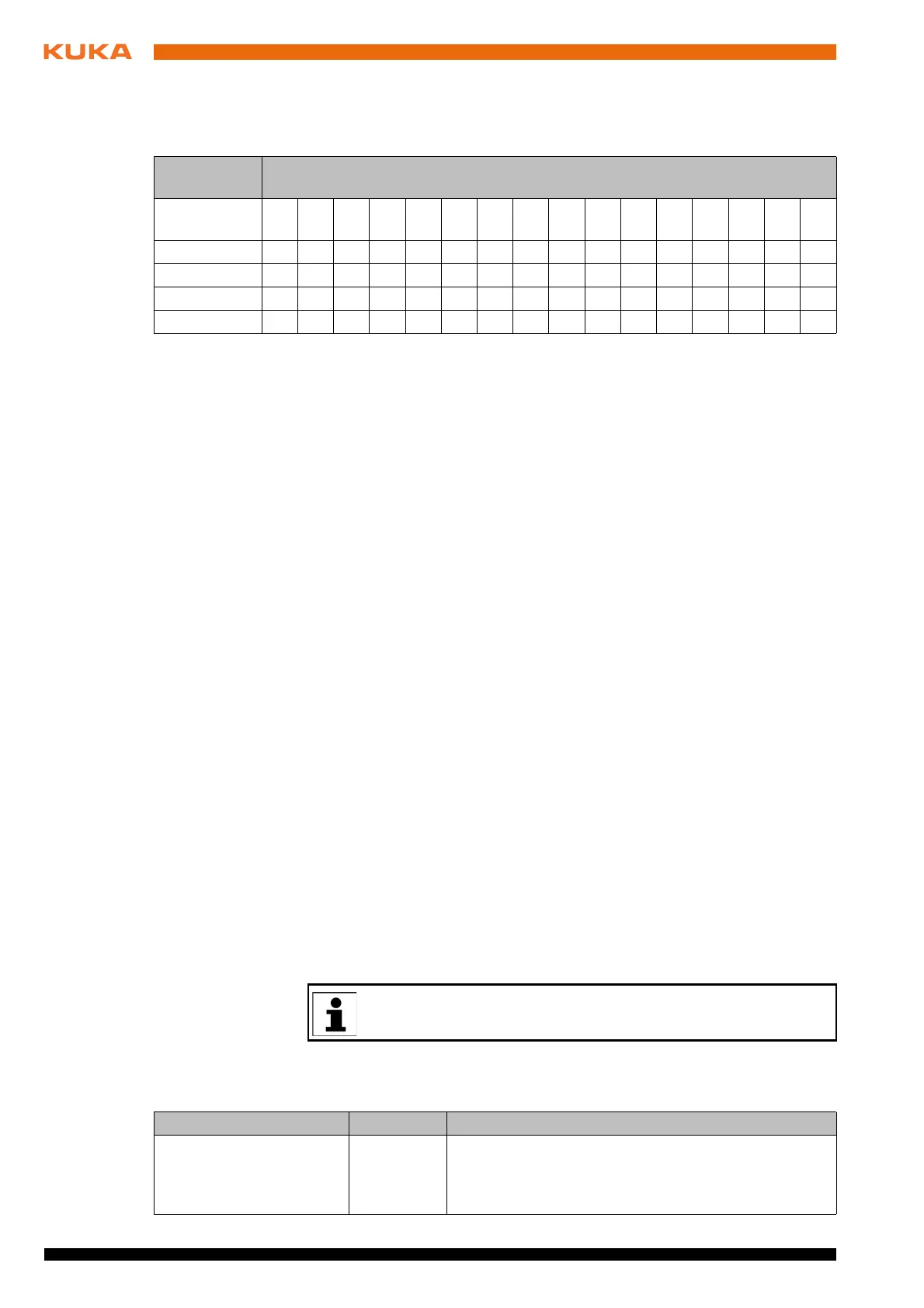
The module can be adapted to special requirements by setting the width of the
parameter channel and the process data length. The following combinations
are possible:
7: Reset response DIP switch 7 determines whether a reset of the lower-level master system trig-
gers a periphery fault in the higher-level system so that it can respond:
OFF: no fault signaled in the higher-level system
ON: fault signaled in the higher-level system
8: Reconfigure
request
DIP switch 8 determines whether a Reconfigure request can be triggered via
the OPC bus terminal:
OFF: no Reconfigure request possible via the OPC bus terminal
ON: Reconfigure request possible via the OPC bus terminal
9: Baud rate DIP switch 9 determines the baud rate of the slave part of the controller board:
OFF: 500 kbaud
ON: 2 Mbaud
10: Configuration
selection
DIP switch 10 determines whether DIP switches 1 to 9 are activated:
OFF: DIP switches 1 to 9 ineffective; parameterization from stored resi-
dent configuration or from configuration received by lower-level master
ON: DIP switches 1 to 9 determine parameterization
6.4 Configuring the file IBSPCI.XML
Description The configuration file IBSPCI.XML contains all the settings which affect the In-
terbus connection.
Precondition
Windows interface
Procedure 1. Open the file C:\KRC\ROBOTER\Config\User\Common\IBSPCI.XML.
2. Check the settings stored in the individual segments and adapt them if re-
quired.
3. Save the changes and close the file.
The file IBSPCI.XML is divided into different sections.
<INTERBUS> section:
Parameter
channel
Process data length (in words)
01234567891
0
11 1
2
1
3
1
4
16
0 words XXXXXXXXXX X XX
1 word XXXXXXXXXX X X
2 words XXXXXXX X X X X
4 words XXXXXXX X X X
Changes must always be made via the main menu Configuration >
Inputs/outputs > I/O drivers.
Entry Value Function
BOARDNUMBER 1 ... 8
Default: 1
Assigns a unique identifier to the controller board for
the data channel. This identifier must match the card
number selected by means of the DIP switches on the
master module.