2FT
1-6-29
(4) Detaching and refitting the laser scanner unit
Take the following procedure when the laser scanner unit is to be replaced.
Procedure
1. Remove the original cover or the DP.
2. Remove the upper right cover, contact
glass, upper rear cover, middle left cover,
upper left cover, slit glass and front scanner
cover (see page 1-6-23).
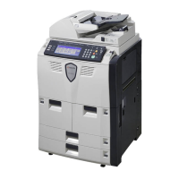
3. Remove the four screws holding the right
cover and then the cover. Remove the
seven screws holding the rear cover and
then the cover.
Figure 1-6-54
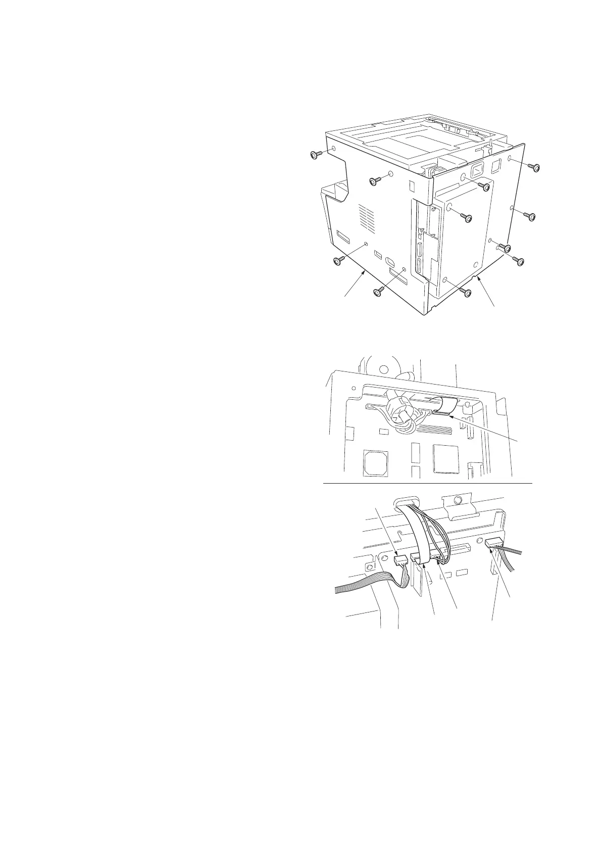
4. Detach the connector YC8 on the main
PCB. Detach the connectors YC16,
YC17,YC18 and YC19 on the engine PCB.
Figure 1-6-55
Rear cover
Right cover
YC8
YC16
YC17
YC18
YC19

 Loading...