2FT
1-3-18
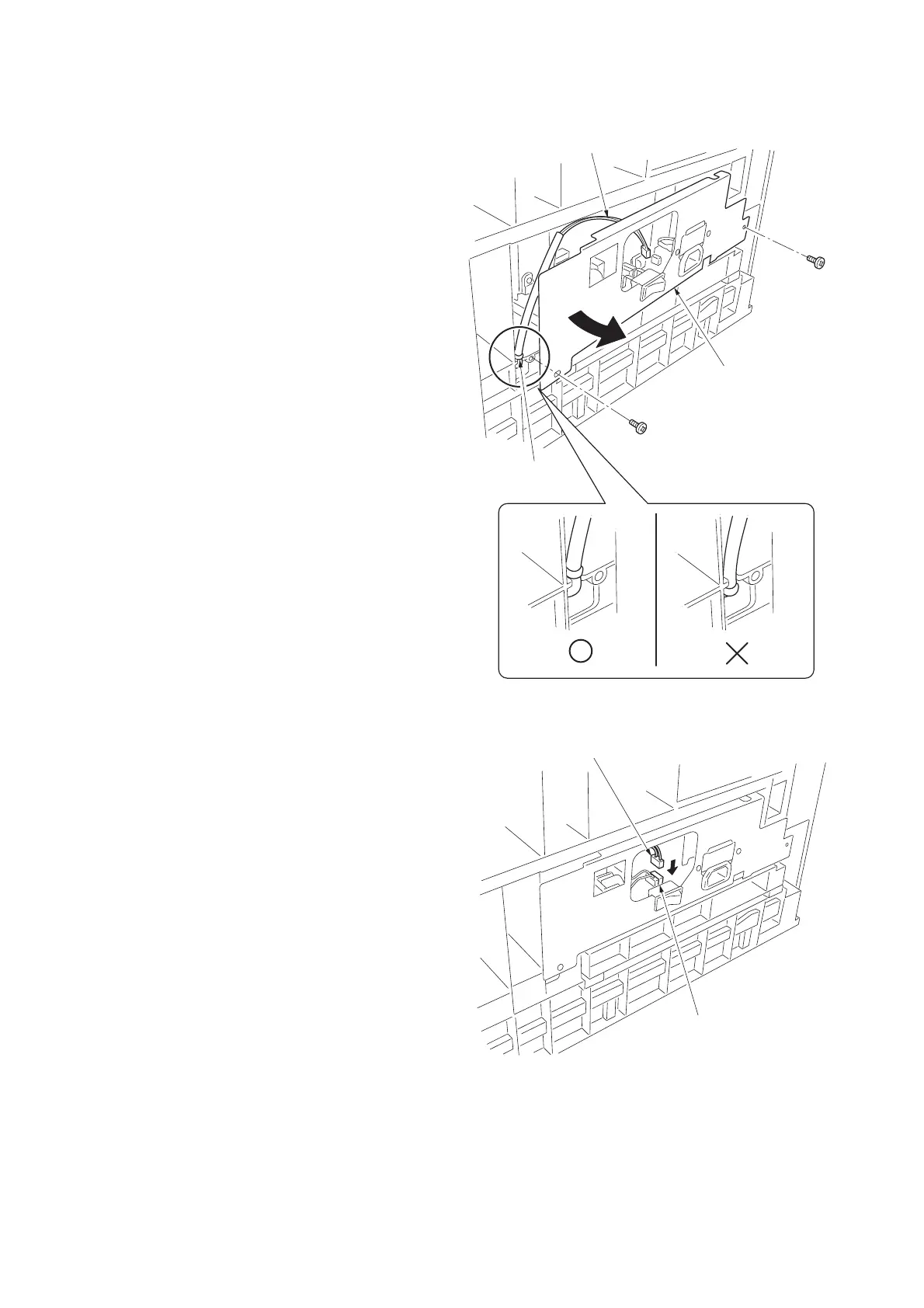
5. Remove the two screws and open the power
source PCB in the direction indicated by the
arrow.
* Take care not to open the power source
PCB too much.
6. Fit the wire of the drawer heater into the
groove of the frame and put it inside the
power source PCB.
* Fit the wire into the groove so that the
band mounted to the wire is located above
the frame.
Figure 1-3-29
7. Reattach the power source PCB to its origi-
nal position and connect the connector of
the drawer heater to YC8 of the power
source PCB.
8. Refit all the removed parts.
Figure 1-3-30
Power source PCB
Wire of the drawer heater
Band
YC8
Connector

 Loading...