KARA_SRM_EN_1-0
w w w . l - a c o u s t i c s . c o m
15
1515
15
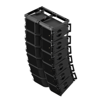
13. Secure the front link points between ARRAY#1 and ARRAY#2 as follows:
a. Slide each KARA#4 front arm up and align it with the KARA#3 front bottom link point.
b. Secure each KARA#4 front arm to KARA#3 by removing the KARA#3 front bottom R-BLP from its storage
hole and re-inserting it into its link hole.
c. Lower the array until KARA#3 and KARA#4 front corners are in contact (keep the front arms vertical).
d. Secure each front arm to KARA#4 by inserting the KARA#4 front top R-BLP into its link hole.
Figure 12: Securing the ARRAY#1 and ARRAY#2 front link points together
14. Raise the array to a height for which the angle arms of ARRAY#2 are within comfortable reach and remove the
flight-case from the rigging location.
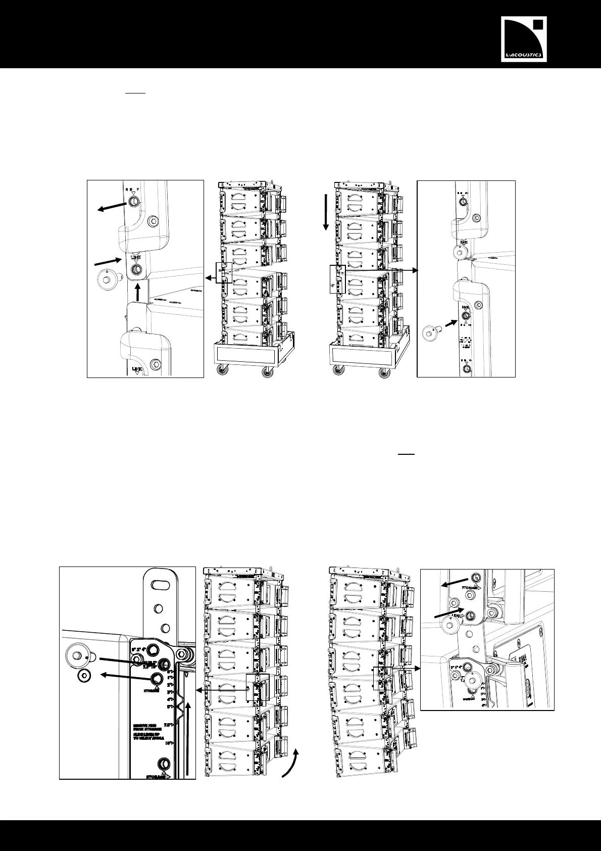
15. With 2 people working simultaneously on each side of the array, secure the rear link points between ARRAY#1
and ARRAY#2 as follows:
a. Remove the KARA#4 rear top R-BLP from its storage hole, slide the angle arm so as to align the cursor with
the chosen angle label, and lock it in place by re-inserting the R-BLP into the corresponding angle hole (0°/2°/4°
or 1°/3°/5°/7.5°/10°).
b. While grabbing the back handle of KARA#6, rotate ARRAY#2 so as to align the KARA#3 and KARA#4 rear
link points.
c. Lock ARRAY#2 in place by removing the KARA#3 rear bottom R-BLP from its storage hole and re-inserting
it into its link hole.
Figure 13: Securing the ARRAY#1 and ARRAY#2 rear link points together
 Loading...