Product Service 1-800-522-7658
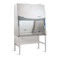
2) Locate the black square connecter labeled as J2 and the white connector labeled
as J3 on the RS-232 PCB, see picture 3. These two connectors show through the
electrical control box as shown in picture 1. Connector J2 is the RS-232 PORT
connector. Connector J3 is the ALARM CONTACT connector. Also note the
location of the J1 connector for later use.
Picture 3
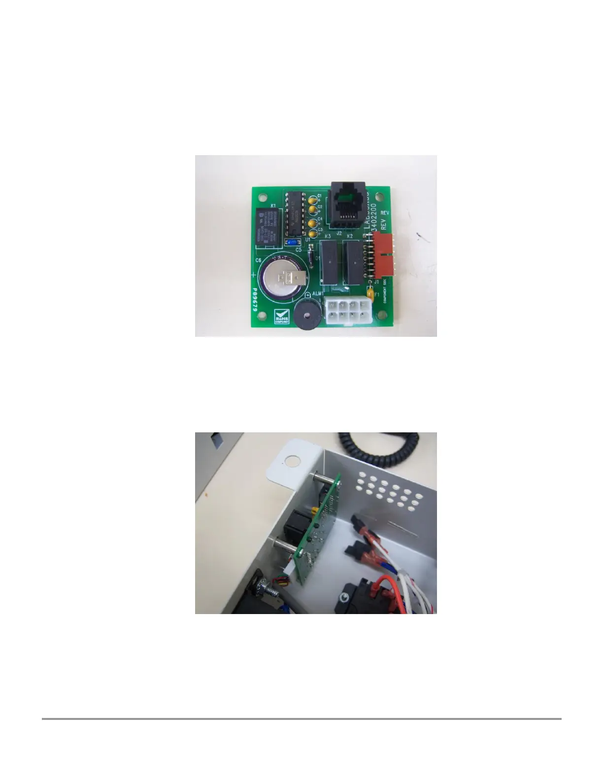
3) Install the RS-232 PCB inside the electrical control box as shown in picture 4,
being careful to locate the J2 connector (found in step 2) thru the square hole
and J3 through the rectangular hole created in step 1. Use the included screws
and lockwashers to attach the PCB to the electrical control box.
Picture 4