EasyManuals Logo
Home>Labconco>Laboratory Equipment>Purifier Logic+ 30132

Labconco Purifier Logic+ 30132 User Manual

Labconco Purifier Logic+ 30132
174 pages
To Next Page IconTo Next Page
To Previous Page IconTo Previous Page
Page #159 background imageLoading...
Page #159 background image
Product Service 1-800-522-7658
159
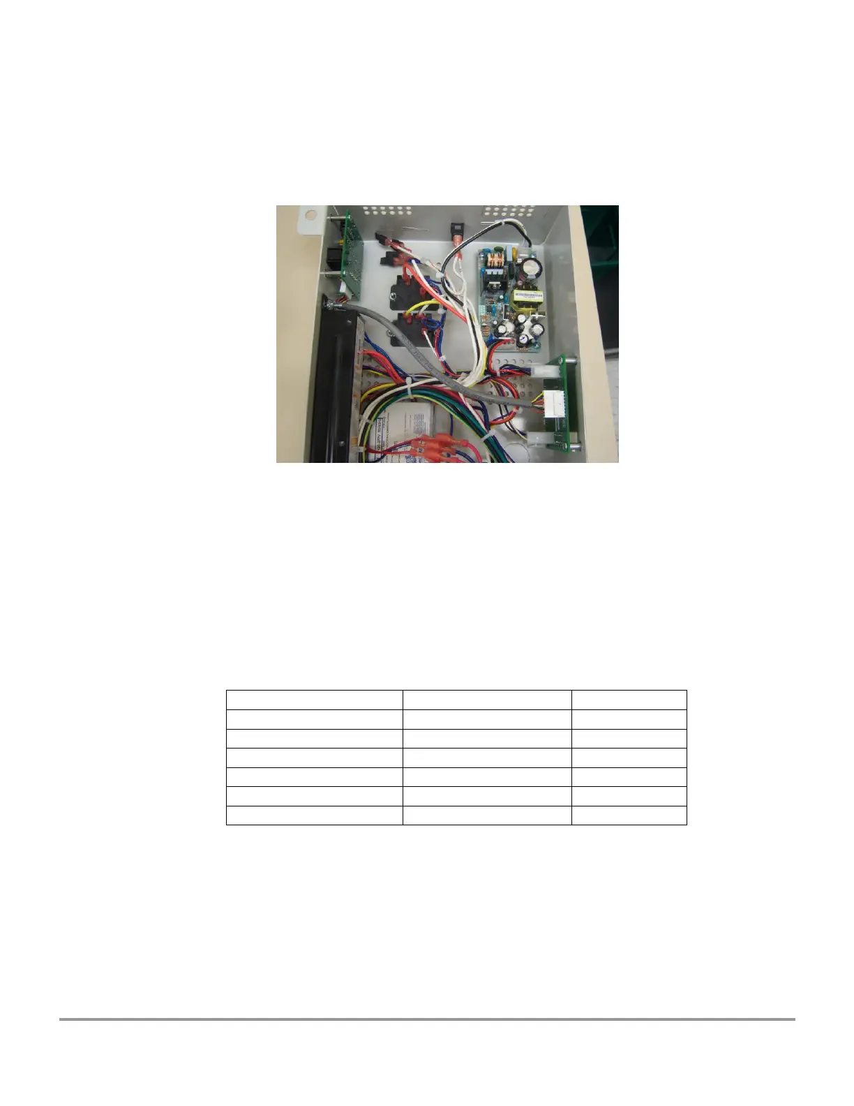
4) Locate the internal RS-232 cable (P/N 3432000) included in the kit and connect it
between the RS-232 PCB J1 and the Transition PCB (P/N 3431500) J6 as shown
in picture 5.
Picture 5
5) Re-secure the electrical control box to the top of the Logic+.
6) Connect the computer interface cable (P/N 7537800 9 pin or P/N 7537801 25
pin) included in the kit to the RS-232 PCB J2 connector, and connect the other
end of this cable to a 9-pin or 25 pin serial input of a computer. Proceed to the
directions “Using the RS-232 Receptacle”.
7) To enable access to the Alarm/Blower contacts connect the alarm/contactor
cable (P/N 3432300) included in the kit to the RS-232 PCB J3 connector. J3 is
shown above the “ALARM CONTACT” label in picture 1.
Signal
Wire Color
J3
ALARM 1 Airflow
ORANGE
1
ALARM 1 - Airflow
ORANGE
2
ALARM 2 - Blower
WHITE
3
ALARM 2 - Blower
WHITE
4
GROUND
BLACK
5
+12V
BLUE
8

Table of Contents

Questions and Answers:

Question and Answer IconNeed help?

Do you have a question about the Labconco Purifier Logic+ 30132 and is the answer not in the manual?

Labconco Purifier Logic+ 30132 Specifications

General IconGeneral
BrandLabconco
ModelPurifier Logic+ 30132
CategoryLaboratory Equipment
LanguageEnglish

Related product manuals